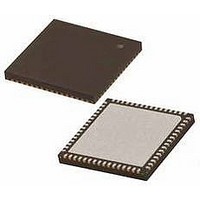
PIC18F65K22-I/MRRSL Microchip Technology, PIC18F65K22-I/MRRSL Datasheet - Page 74

PIC18F65K22-I/MRRSL
Manufacturer Part Number
PIC18F65K22-I/MRRSL
Description
MCU PIC 32K FLASH MEM XLP 64QFN
Manufacturer
Microchip Technology
Series
PIC® XLP™ 18Fr
Datasheets
1.PIC16F722-ISS.pdf
(8 pages)
2.PIC18F65K22T-IPTRSL.pdf
(548 pages)
3.PIC18F65K22T-IPTRSL.pdf
(10 pages)
Specifications of PIC18F65K22-I/MRRSL
Core Size
8-Bit
Program Memory Size
32KB (16K x 16)
Core Processor
PIC
Speed
64MHz
Connectivity
I²C, LIN, SPI, UART/USART
Peripherals
Brown-out Detect/Reset, LVD, POR, PWM, WDT
Number Of I /o
53
Program Memory Type
FLASH
Eeprom Size
1K x 8
Ram Size
2K x 8
Voltage - Supply (vcc/vdd)
1.8 V ~ 5.5 V
Data Converters
A/D 16x12b
Oscillator Type
Internal
Operating Temperature
-40°C ~ 85°C
Package / Case
64-VFQFN, Exposed Pad
Controller Family/series
PIC18
No. Of I/o's
53
Eeprom Memory Size
1KB
Ram Memory Size
2KB
Cpu Speed
64MHz
No. Of Timers
8
Processor Series
PIC18F
Core
PIC
Data Bus Width
8 bit
Data Ram Size
2 KB
Interface Type
I2C, SPI
Maximum Clock Frequency
64 MHz
Number Of Programmable I/os
53
Number Of Timers
8
Operating Supply Voltage
1.8 V to 5.5 V
Maximum Operating Temperature
+ 125 C
Mounting Style
SMD/SMT
3rd Party Development Tools
52715-96, 52716-328, 52717-734, 52712-325, EWPIC18
Minimum Operating Temperature
- 40 C
On-chip Adc
12 bit, 16 Channel
Lead Free Status / RoHS Status
Lead free / RoHS Compliant
Lead Free Status / RoHS Status
Lead free / RoHS Compliant
- PIC16F722-ISS PDF datasheet
- PIC18F65K22T-IPTRSL PDF datasheet #2
- PIC18F65K22T-IPTRSL PDF datasheet #3
- Current page: 74 of 548
- Download datasheet (5Mb)
PIC18F87K22 FAMILY
5.5
The Configuration Mismatch (CM) Reset is designed to
detect, and attempt to recover from, random, memory
corrupting events. These include Electrostatic Discharge
(ESD) events that can cause widespread, single bit
changes throughout the device and result in catastrophic
failure.
In PIC18F87K22 family Flash devices, the device
Configuration registers (located in the configuration
memory space) are continuously monitored during
operation by comparing their values to complimentary
shadow registers. If a mismatch is detected between
the two sets of registers, a CM Reset automatically
occurs. These events are captured by the CM bit
(RCON<5>). The state of the bit is set to ‘0’ whenever
a CM event occurs and does not change for any other
Reset event.
A CM Reset behaves similarly to a Master Clear Reset,
RESET instruction, WDT time-out or Stack Event Reset.
As with all hard and power Reset events, the device
Configuration Words are reloaded from the Flash
Configuration Words in program memory as the device
restarts.
FIGURE 5-3:
DS39960B-page 74
INTERNAL RESET
PWRT TIME-OUT
INTERNAL POR
Configuration Mismatch (CM)
MCLR
V
DD
TIME-OUT SEQUENCE ON POWER-UP (MCLR TIED TO V
Preliminary
T
PWRT
5.6
PIC18F87K22 family devices incorporate an on-chip
Power-up Timer (PWRT) to help regulate the Power-on
Reset process. The PWRT is enabled by setting the
PWRTEN bit (CONFIG2L<0>). The main function is to
ensure that the device voltage is stable before code is
executed.
The Power-up Timer (PWRT) of the PIC18F87K22
family devices is a 13-bit counter that uses the
LF-INTOSC source as the clock input. This yields an
approximate time interval of 2,048 x 32 s = 66 ms.
While the PWRT is counting, the device is held in
Reset.
The power-up time delay depends on the LF-INTOSC
clock and will vary from chip-to-chip due to temperature
and process variation. See DC parameter 33 for
details.
5.6.1
If enabled, the PWRT time-out is invoked after the POR
pulse has cleared. The total time-out will vary based on
the status of the PWRT. Figure 5-3, Figure 5-4,
Figure 5-5
sequences on power-up with the Power-up Timer
enabled.
Since the time-outs occur from the POR pulse, if
MCLR is kept low long enough, the PWRT will expire.
Bringing MCLR high will begin execution immediately
(Figure 5-5). This is useful for testing purposes, or for
synchronizing more than one PIC18 device operating
in parallel.
Power-up Timer (PWRT)
TIME-OUT SEQUENCE
and
Figure 5-6
2010 Microchip Technology Inc.
DD
, V
DD
all
RISE < T
depict
PWRT
time-out
)
Related parts for PIC18F65K22-I/MRRSL
Image
Part Number
Description
Manufacturer
Datasheet
Request
R

Part Number:
Description:
MCU PIC 32K FLASH MEM XLP 64TQFP
Manufacturer:
Microchip Technology
Datasheet:

Part Number:
Description:
32kB Flash, 2kB RAM, 1kB EE, NanoWatt XLP, GP 64 QFN 9x9x0.9mm TUBE
Manufacturer:
Microchip Technology
Datasheet:

Part Number:
Description:
32kB Flash, 2kB RAM, 1kB EE, NanoWatt XLP, GP 64 TQFP 10x10x1mm TRAY
Manufacturer:
Microchip Technology
Datasheet:

Part Number:
Description:
32kB Flash, 2kB RAM, 1kB EE, NanoWatt XLP, GP 64 QFN 9x9x0.9mm TUBE
Manufacturer:
Microchip Technology
Datasheet:

Part Number:
Description:
32kB Flash, 2kB RAM, 1kB EE, NanoWatt XLP, GP 64 TQFP 10x10x1mm TRAY
Manufacturer:
Microchip Technology

Part Number:
Description:
Manufacturer:
Microchip Technology Inc.
Datasheet:

Part Number:
Description:
Manufacturer:
Microchip Technology Inc.
Datasheet:

Part Number:
Description:
Manufacturer:
Microchip Technology Inc.
Datasheet:

Part Number:
Description:
Manufacturer:
Microchip Technology Inc.
Datasheet:

Part Number:
Description:
Manufacturer:
Microchip Technology Inc.
Datasheet:

Part Number:
Description:
Manufacturer:
Microchip Technology Inc.
Datasheet:


