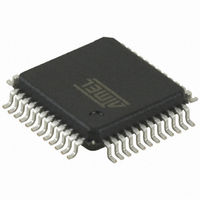
AT32UC3B164-AUT Atmel, AT32UC3B164-AUT Datasheet - Page 450

AT32UC3B164-AUT
Manufacturer Part Number
AT32UC3B164-AUT
Description
IC MCU AVR32 64KB FLASH 48-TQFP
Manufacturer
Atmel
Series
AVR®32 UC3r
Specifications of AT32UC3B164-AUT
Core Processor
AVR
Core Size
32-Bit
Speed
60MHz
Connectivity
I²C, IrDA, SPI, SSC, UART/USART, USB
Peripherals
Brown-out Detect/Reset, DMA, POR, PWM, WDT
Number Of I /o
28
Program Memory Size
64KB (64K x 8)
Program Memory Type
FLASH
Ram Size
16K x 8
Voltage - Supply (vcc/vdd)
1.65 V ~ 1.95 V
Data Converters
A/D 6x10b
Oscillator Type
Internal
Operating Temperature
-40°C ~ 85°C
Package / Case
48-TQFP, 48-VQFP
Controller Family/series
AT32UC3B
No. Of I/o's
28
Ram Memory Size
16KB
Cpu Speed
60MHz
No. Of Timers
1
Rohs Compliant
Yes
For Use With
ATSTK600-TQFP48 - STK600 SOCKET/ADAPTER 48-TQFPATAVRONEKIT - KIT AVR/AVR32 DEBUGGER/PROGRMMR770-1008 - ISP 4PORT ATMEL AVR32 MCU SPIATEVK1101 - KIT DEV/EVAL FOR AVR32 AT32UC3B
Lead Free Status / RoHS Status
Lead free / RoHS Compliant
Eeprom Size
-
Available stocks
Company
Part Number
Manufacturer
Quantity
Price
- Current page: 450 of 676
- Download datasheet (11Mb)
22.8.2.19
Register Name:
Access Type:
Offset:
Reset Value:
•
•
•
•
•
•
32059I–06/2010
BURSTLOCKEN
CHBYTELENGTH: Channel Byte Length
BURSTLOCKEN: Burst Lock Enable
DESCLDIRQEN: Descriptor Loaded Interrupt Enable
EOBUFFIRQEN: End of Buffer Interrupt Enable
EOTIRQEN: End of USB Transfer Interrupt Enable
DMAENDEN: End of DMA Buffer Output Enable
31
23
15
7
-
This field determines the total number of bytes to be transferred for this buffer.
The maximum channel transfer size 64kB is reached when this field is zero (default value).
If the transfer size is unknown, the transfer end is controlled by the peripheral and this field should be written to zero.
This field can be written or descriptor loading only after the UDDMAnSTATUS.CHEN bit has been cleared, otherwise this field is
1: The USB data burst is locked for maximum optimization of HSB busses bandwidth usage and maximization of fly-by duration.
0: The DMA never locks the HSB access.
1: The Descriptor Loaded interrupt is enabled.This interrupt is generated when a Descriptor has been loaded from the system
0: The Descriptor Loaded interrupt is disabled.
1: The end of buffer interrupt is enabled.This interrupt is generated when the channel byte count reaches zero.
0: The end of buffer interrupt is disabled.
1: The end of usb OUT data transfer interrupt is enabled. This interrupt is generated only if the BUFFCLOSEINEN bit is set.
0: The end of usb OUT data transfer interrupt is disabled.
Writing a one to this bit will properly complete the usb transfer at the end of the dma transfer.
For IN endpoint, it means that a short packet (or a Zero Length Packet) will be sent to the USB line to properly closed the usb
For OUT endpoint, it means that all the banks will be properly released. (NBUSYBK=0) at the end of the dma transfer.
ignored.
bus.
transfer at the end of the dma transfer.
Device DMA Channel n Control Register
DESCLDIRQEN
30
22
14
6
-
UDDMAnCONTROL, n in [1..6]
Read/Write
0x0318 + (n - 1) * 0x10
0x00000000
EOBUFFIRQEN
29
21
13
5
-
EOTIRQEN
CHBYTELENGTH[15:8]
CHBYTELENGTH[7:0]
28
20
12
4
-
DMAENDEN
27
19
11
3
-
BUFFCLOSE
INEN
26
18
10
2
-
LDNXTCH
DESCEN
25
17
9
1
-
AT32UC3B
CHEN
24
16
8
0
-
450
Related parts for AT32UC3B164-AUT
Image
Part Number
Description
Manufacturer
Datasheet
Request
R

Part Number:
Description:
DEV KIT FOR AVR/AVR32
Manufacturer:
Atmel
Datasheet:

Part Number:
Description:
INTERVAL AND WIPE/WASH WIPER CONTROL IC WITH DELAY
Manufacturer:
ATMEL Corporation
Datasheet:

Part Number:
Description:
Low-Voltage Voice-Switched IC for Hands-Free Operation
Manufacturer:
ATMEL Corporation
Datasheet:

Part Number:
Description:
MONOLITHIC INTEGRATED FEATUREPHONE CIRCUIT
Manufacturer:
ATMEL Corporation
Datasheet:

Part Number:
Description:
AM-FM Receiver IC U4255BM-M
Manufacturer:
ATMEL Corporation
Datasheet:

Part Number:
Description:
Monolithic Integrated Feature Phone Circuit
Manufacturer:
ATMEL Corporation
Datasheet:

Part Number:
Description:
Multistandard Video-IF and Quasi Parallel Sound Processing
Manufacturer:
ATMEL Corporation
Datasheet:

Part Number:
Description:
High-performance EE PLD
Manufacturer:
ATMEL Corporation
Datasheet:

Part Number:
Description:
8-bit Flash Microcontroller
Manufacturer:
ATMEL Corporation
Datasheet:

Part Number:
Description:
2-Wire Serial EEPROM
Manufacturer:
ATMEL Corporation
Datasheet:


