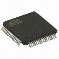
AT32UC3B0256-A2UR Atmel, AT32UC3B0256-A2UR Datasheet - Page 341

AT32UC3B0256-A2UR
Manufacturer Part Number
AT32UC3B0256-A2UR
Description
MCU AVR32 256K FLASH 64-TQFP
Manufacturer
Atmel
Series
AVR®32 UC3r
Datasheet
1.AT32UC3B1512-Z1UT.pdf
(692 pages)
Specifications of AT32UC3B0256-A2UR
Package / Case
64-TQFP, 64-VQFP
Voltage - Supply (vcc/vdd)
1.65 V ~ 1.95 V
Operating Temperature
-40°C ~ 85°C
Speed
60MHz
Number Of I /o
44
Core Processor
AVR
Program Memory Type
FLASH
Ram Size
32K x 8
Program Memory Size
256KB (256K x 8)
Data Converters
A/D 8x10b
Oscillator Type
Internal
Peripherals
Brown-out Detect/Reset, DMA, POR, PWM, WDT
Connectivity
I²C, IrDA, SPI, SSC, UART/USART, USB
Core Size
32-Bit
Package
64TQFP
Device Core
AVR32
Family Name
AT32
Maximum Speed
60 MHz
Operating Supply Voltage
1.8|3.3 V
Data Bus Width
32 Bit
Number Of Programmable I/os
44
Interface Type
I2S/SPI/TWI/USART/USB
On-chip Adc
8-chx10-bit
Number Of Timers
3
Lead Free Status / RoHS Status
Lead free / RoHS Compliant
Eeprom Size
-
Available stocks
Company
Part Number
Manufacturer
Quantity
Price
- Current page: 341 of 692
- Download datasheet (11Mb)
•
•
•
•
Table 21-15.
•
Table 21-16.
•
Table 21-17.
32059K–03/2011
CLKO: Clock Output Select
MODE9: 9-bit Character Length
MSBF/CPOL: Bit Order or SPI Clock Polarity
CHMODE: Channel Mode
NBSTOP: Number of Stop Bits
PAR: Parity Type
0
0
1
1
0
0
1
1
0
0
0
0
1
1
CHMODE
NBSTOP
0: The USART does not drive the CLK pin.
1: The USART drives the CLK pin if USCLKS does not select the external clock CLK.
0: CHRL defines character length.
1: 9-bit character length.
If USART does not operate in SPI Mode (MODE … 0xE and 0xF):
MSBF = 0: Least Significant Bit is sent/received first.
MSBF = 1: Most Significant Bit is sent/received first.
If USART operates in SPI Mode (Slave or Master, MODE = 0xE or 0xF):
CPOL = 0: The inactive state value of SPCK is logic level zero.
CPOL = 1: The inactive state value of SPCK is logic level one.
CPOL is used to determine the inactive state value of the serial clock (SPCK). It is used with CPHA to produce the required
clock/data relationship between master and slave devices.
PAR
0
1
0
1
0
1
0
1
0
0
1
1
0
1
Mode Description
Normal Mode
Automatic Echo. Receiver input is connected to the TXD pin.
Local Loopback. Transmitter output is connected to the Receiver Input.
Remote Loopback. RXD pin is internally connected to the TXD pin.
Asynchronous (SYNC = 0)
1 stop bit
1.5 stop bits
2 stop bits
Reserved
0
1
0
1
x
x
Parity Type
Even parity
Odd parity
Parity forced to 0 (Space)
Parity forced to 1 (Mark)
No parity
Multidrop mode
Synchronous (SYNC = 1)
1 stop bit
Reserved
2 stop bits
Reserved
AT32UC3B
341
Related parts for AT32UC3B0256-A2UR
Image
Part Number
Description
Manufacturer
Datasheet
Request
R

Part Number:
Description:
DEV KIT FOR AVR/AVR32
Manufacturer:
Atmel
Datasheet:

Part Number:
Description:
INTERVAL AND WIPE/WASH WIPER CONTROL IC WITH DELAY
Manufacturer:
ATMEL Corporation
Datasheet:

Part Number:
Description:
Low-Voltage Voice-Switched IC for Hands-Free Operation
Manufacturer:
ATMEL Corporation
Datasheet:

Part Number:
Description:
MONOLITHIC INTEGRATED FEATUREPHONE CIRCUIT
Manufacturer:
ATMEL Corporation
Datasheet:

Part Number:
Description:
AM-FM Receiver IC U4255BM-M
Manufacturer:
ATMEL Corporation
Datasheet:

Part Number:
Description:
Monolithic Integrated Feature Phone Circuit
Manufacturer:
ATMEL Corporation
Datasheet:

Part Number:
Description:
Multistandard Video-IF and Quasi Parallel Sound Processing
Manufacturer:
ATMEL Corporation
Datasheet:

Part Number:
Description:
High-performance EE PLD
Manufacturer:
ATMEL Corporation
Datasheet:

Part Number:
Description:
8-bit Flash Microcontroller
Manufacturer:
ATMEL Corporation
Datasheet:

Part Number:
Description:
2-Wire Serial EEPROM
Manufacturer:
ATMEL Corporation
Datasheet:


