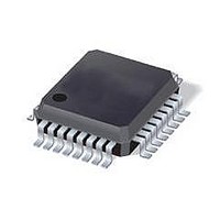
ST7FOXK1T6TR STMicroelectronics, ST7FOXK1T6TR Datasheet - Page 183

ST7FOXK1T6TR
Manufacturer Part Number
ST7FOXK1T6TR
Description
IC MCU 8BIT 4K FLASH 20LQFP
Manufacturer
STMicroelectronics
Series
ST7r
Datasheet
1.ST7FOXF1M6.pdf
(226 pages)
Specifications of ST7FOXK1T6TR
Core Processor
ST7
Core Size
8-Bit
Speed
8MHz
Connectivity
I²C
Peripherals
LVD, POR, PWM, WDT
Number Of I /o
24
Program Memory Size
4KB (4K x 8)
Program Memory Type
FLASH
Ram Size
384 x 8
Voltage - Supply (vcc/vdd)
4.5 V ~ 5.5 V
Data Converters
A/D 10x10b
Oscillator Type
Internal
Operating Temperature
-40°C ~ 85°C
Package / Case
32-LQFP
Processor Series
ST7FOXx
Core
ST7
Data Bus Width
8 bit
Data Ram Size
384 B
Interface Type
I2C
Maximum Clock Frequency
8 MHz
Number Of Programmable I/os
24
Number Of Timers
4
Maximum Operating Temperature
+ 85 C
Mounting Style
SMD/SMT
Development Tools By Supplier
ST7FLITE-SK/RAIS, STX-RLINK
Minimum Operating Temperature
- 40 C
On-chip Adc
10 bit, 1 Channel
For Use With
497-5049 - KIT STARTER RAISONANCE ST7FLITE
Lead Free Status / RoHS Status
Lead free / RoHS Compliant
Eeprom Size
-
Lead Free Status / Rohs Status
Details
Available stocks
Company
Part Number
Manufacturer
Quantity
Price
Company:
Part Number:
ST7FOXK1T6TR
Manufacturer:
STMicroelectronics
Quantity:
10 000
- Current page: 183 of 226
- Download datasheet (4Mb)
ST7FOXF1, ST7FOXK1, ST7FOXK2
11.2
Instruction groups
The ST7 family devices use an Instruction Set consisting of 63 instructions. The instructions
may be subdivided into 13 main groups as illustrated in the following table:
Table 64.
Using a prebyte
The instructions are described with 1 to 4 bytes.
In order to extend the number of available opcodes for an 8-bit CPU (256 opcodes), three
different prebyte opcodes are defined. These prebytes modify the meaning of the instruction
they precede.
The whole instruction becomes by:
These prebytes enable instruction in Y as well as indirect addressing modes to be
implemented. They precede the opcode of the instruction in X or the instruction using direct
addressing mode. The prebytes are:
Condition Code Flag modification
Conditional bit test and branch
Unconditional jump or call
PC-2 End of previous instruction
PC-1 Prebyte
PC Opcode
PC+1 Additional word (0 to 2) according to the number of bytes required to compute
the effective address
PDY 90 Replace an X based instruction using immediate, direct, indexed, or inherent
addressing mode by a Y one.
PIX 92 Replace an instruction using direct, direct bit or direct relative addressing mode
to an instruction using the corresponding indirect addressing mode.
It also changes an instruction using X indexed addressing mode to an instruction using
indirect X indexed addressing mode.
PIY 91 Replace an instruction using X indirect indexed addressing mode by a Y one.
Interruption management
Increment/decrement
Arithmetic operations
Compare and tests
Conditional branch
Logical operations
Load and Transfer
Stack operation
Shift and rotate
Bit operation
ST7 instruction set
PUSH
BSET
TRAP
BTJT
JRxx
AND
ADC
SLL
JRA
INC
SIM
CP
LD
BRES
BTJF
POP
DEC
ADD
CLR
TNZ
SRL
JRT
WFI
RIM
OR
HALT
XOR
RSP
BCP
SUB
SRA
SCF
JRF
IRET
SBC
RLC
RCF
CPL
JP
CALL
NEG
MUL
RRC
CALLR
SWAP
Instruction set
NOP RET
SLA
183/226
Related parts for ST7FOXK1T6TR
Image
Part Number
Description
Manufacturer
Datasheet
Request
R

Part Number:
Description:
Low cost flash 8bit micro
Manufacturer:
STMicroelectronics
Datasheet:

Part Number:
Description:
STMicroelectronics [RIPPLE-CARRY BINARY COUNTER/DIVIDERS]
Manufacturer:
STMicroelectronics
Datasheet:

Part Number:
Description:
STMicroelectronics [LIQUID-CRYSTAL DISPLAY DRIVERS]
Manufacturer:
STMicroelectronics
Datasheet:

Part Number:
Description:
BOARD EVAL FOR MEMS SENSORS
Manufacturer:
STMicroelectronics
Datasheet:

Part Number:
Description:
NPN TRANSISTOR POWER MODULE
Manufacturer:
STMicroelectronics
Datasheet:

Part Number:
Description:
TURBOSWITCH ULTRA-FAST HIGH VOLTAGE DIODE
Manufacturer:
STMicroelectronics
Datasheet:

Part Number:
Description:
Manufacturer:
STMicroelectronics
Datasheet:

Part Number:
Description:
DIODE / SCR MODULE
Manufacturer:
STMicroelectronics
Datasheet:

Part Number:
Description:
DIODE / SCR MODULE
Manufacturer:
STMicroelectronics
Datasheet:

Part Number:
Description:
Search -----> STE16N100
Manufacturer:
STMicroelectronics
Datasheet:

Part Number:
Description:
Search ---> STE53NA50
Manufacturer:
STMicroelectronics
Datasheet:

Part Number:
Description:
NPN Transistor Power Module
Manufacturer:
STMicroelectronics
Datasheet:


