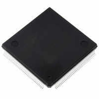
ST10F276Z5Q3TR STMicroelectronics, ST10F276Z5Q3TR Datasheet - Page 189

ST10F276Z5Q3TR
Manufacturer Part Number
ST10F276Z5Q3TR
Description
MCU 16BIT 832KBIT FLASH 144-PQFP
Manufacturer
STMicroelectronics
Series
ST10r
Datasheet
1.ST10F276Z5T3.pdf
(239 pages)
Specifications of ST10F276Z5Q3TR
Core Processor
ST10
Core Size
16-Bit
Speed
64MHz
Connectivity
ASC, CAN, EBI/EMI, I²C, SSC, UART/USART
Peripherals
POR, PWM, WDT
Number Of I /o
111
Program Memory Size
832KB (832K x 8)
Program Memory Type
FLASH
Ram Size
68K x 8
Voltage - Supply (vcc/vdd)
4.5 V ~ 5.5 V
Data Converters
A/D 24x10b
Oscillator Type
Internal
Operating Temperature
-40°C ~ 125°C
Package / Case
144-QFP
Processor Series
ST10F27x
Core
ST10
Data Bus Width
16 bit
Data Ram Size
68 KB
Interface Type
CAN, I2C
Maximum Clock Frequency
64 MHz
Number Of Programmable I/os
111
Number Of Timers
5
Maximum Operating Temperature
+ 125 C
Mounting Style
SMD/SMT
Minimum Operating Temperature
- 40 C
On-chip Adc
10 bit, 24 Channel
For Use With
497-6399 - KIT DEV STARTER ST10F276Z5
Lead Free Status / RoHS Status
Lead free / RoHS Compliant
Eeprom Size
-
Lead Free Status / Rohs Status
Details
Available stocks
Company
Part Number
Manufacturer
Quantity
Price
Company:
Part Number:
ST10F276Z5Q3TR
Manufacturer:
STMicroelectronics
Quantity:
10 000
- Current page: 189 of 239
- Download datasheet (3Mb)
ST10F276Z5
Note:
23.7.2
Table 96.
The total conversion time is compatible with the formula valid for ST10F269, while the
meaning of the bit fields ADCTC and ADSTC is no longer compatible: The minimum
conversion time is 388 TCL, which at 40 MHz CPU frequency corresponds to 4.85
ST10F269).
A/D conversion accuracy
The A/D converter compares the analog voltage sampled on the selected analog input
channel to its analog reference voltage (V
absolute accuracy of the A/D conversion is the deviation between the input analog value and
the output digital value. It includes the following errors:
These four error quantities are explained below using
Offset error
Offset error is the deviation between actual and ideal A/D conversion characteristics when
the digital output value changes from the minimum (zero voltage) 00 to 01
OFS).
Gain error
Gain error is the deviation between the actual and ideal A/D conversion characteristics when
the digital output value changes from the 3FE to the maximum 3FF, once offset error is sub-
tracted. Gain error combined with offset error represents the so-called full-scale error
(Figure
Quantization error
Quantization error is the intrinsic error of the A/D converter and is expressed as 1/2 LSB.
00
00
11
11
11
11
10
10
10
10
ADCTC
–
–
–
–
46, OFS + GE).
Offset error (OFS)
Gain error (GE)
Quantization error
Nonlinearity error (differential and integral)
10
11
00
01
10
11
00
01
10
11
ADSTC
A/D Converter programming (continued)
TCL * 200
TCL * 400
TCL * 240
TCL * 280
TCL * 400
TCL * 800
TCL * 480
TCL * 560
TCL * 800
TCL * 1600
Sample
TCL * 280
TCL * 280
TCL * 480
TCL * 560
TCL * 560
TCL * 560
TCL * 960
TCL * 1120
TCL * 1120
TCL * 1120
Comparison
AREF
) and converts it into 10-bit digital data. The
Figure
TCL * 52
TCL * 44
TCL * 52
TCL * 28
TCL * 100
TCL * 52
TCL * 100
TCL * 52
TCL * 196
TCL * 164
46.
Extra
Electrical characteristics
TCL * 532
TCL * 724
TCL * 772
TCL * 868
TCL * 1060
TCL * 1444
TCL * 1540
TCL * 1732
TCL * 2116
TCL * 2884
(Figure
Total conversion
µ
46, see
s (see
189/239
Related parts for ST10F276Z5Q3TR
Image
Part Number
Description
Manufacturer
Datasheet
Request
R

Part Number:
Description:
MCU 16BIT 832K FLASH 144-LQFP
Manufacturer:
STMicroelectronics
Datasheet:

Part Number:
Description:
MCU 16BIT 832K FLASH 144-LQFP
Manufacturer:
STMicroelectronics
Datasheet:

Part Number:
Description:
MCU 16BIT 832K FLASH 144-PQFP
Manufacturer:
STMicroelectronics
Datasheet:

Part Number:
Description:
MCU 16BIT 832K FLASH 144-PQFP
Manufacturer:
STMicroelectronics
Datasheet:

Part Number:
Description:
16-bit Microcontrollers - MCU 16-Bit MCU 832 kByte 68 KB RAM CMOS
Manufacturer:
STMicroelectronics

Part Number:
Description:
STMicroelectronics [RIPPLE-CARRY BINARY COUNTER/DIVIDERS]
Manufacturer:
STMicroelectronics
Datasheet:

Part Number:
Description:
STMicroelectronics [LIQUID-CRYSTAL DISPLAY DRIVERS]
Manufacturer:
STMicroelectronics
Datasheet:

Part Number:
Description:
BOARD EVAL FOR MEMS SENSORS
Manufacturer:
STMicroelectronics
Datasheet:

Part Number:
Description:
NPN TRANSISTOR POWER MODULE
Manufacturer:
STMicroelectronics
Datasheet:

Part Number:
Description:
TURBOSWITCH ULTRA-FAST HIGH VOLTAGE DIODE
Manufacturer:
STMicroelectronics
Datasheet:

Part Number:
Description:
Manufacturer:
STMicroelectronics
Datasheet:

Part Number:
Description:
DIODE / SCR MODULE
Manufacturer:
STMicroelectronics
Datasheet:


