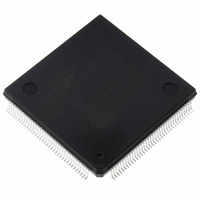
ST10F276Z5Q3TR STMicroelectronics, ST10F276Z5Q3TR Datasheet - Page 196

ST10F276Z5Q3TR
Manufacturer Part Number
ST10F276Z5Q3TR
Description
MCU 16BIT 832KBIT FLASH 144-PQFP
Manufacturer
STMicroelectronics
Series
ST10r
Datasheet
1.ST10F276Z5T3.pdf
(239 pages)
Specifications of ST10F276Z5Q3TR
Core Processor
ST10
Core Size
16-Bit
Speed
64MHz
Connectivity
ASC, CAN, EBI/EMI, I²C, SSC, UART/USART
Peripherals
POR, PWM, WDT
Number Of I /o
111
Program Memory Size
832KB (832K x 8)
Program Memory Type
FLASH
Ram Size
68K x 8
Voltage - Supply (vcc/vdd)
4.5 V ~ 5.5 V
Data Converters
A/D 24x10b
Oscillator Type
Internal
Operating Temperature
-40°C ~ 125°C
Package / Case
144-QFP
Processor Series
ST10F27x
Core
ST10
Data Bus Width
16 bit
Data Ram Size
68 KB
Interface Type
CAN, I2C
Maximum Clock Frequency
64 MHz
Number Of Programmable I/os
111
Number Of Timers
5
Maximum Operating Temperature
+ 125 C
Mounting Style
SMD/SMT
Minimum Operating Temperature
- 40 C
On-chip Adc
10 bit, 24 Channel
For Use With
497-6399 - KIT DEV STARTER ST10F276Z5
Lead Free Status / RoHS Status
Lead free / RoHS Compliant
Eeprom Size
-
Lead Free Status / Rohs Status
Details
Available stocks
Company
Part Number
Manufacturer
Quantity
Price
Company:
Part Number:
ST10F276Z5Q3TR
Manufacturer:
STMicroelectronics
Quantity:
10 000
- Current page: 196 of 239
- Download datasheet (3Mb)
Electrical characteristics
23.8
23.8.1
196/239
then half a count (considering the worst case when V
The other conditions to verify are if the time constants of the transients are really and
significantly shorter than the sampling period duration T
For a complete set of parameters characterizing the ST10F276Z5 A/D converter equivalent
circuit, refer to A/D Converter Characteristics table at page 187.
AC characteristics
Test waveforms
Figure 50. Input/output waveforms
Figure 51. Float waveforms
V
LOAD
For timing purposes a port pin is no longer floating when V
It begins to float when a 100mV change from the loaded V
V
V
0.4 V
LOAD
LOAD
2.4 V
+ 0.1 V
- 0.1 V
AC inputs during testing are driven at 2.4 V for a logic ‘1’ and 0.4 V for a logic ‘0’.
Timing measurements are made at V
V
10 τ
A
⋅
R
------------------------------------------------------------------------ -
τ
⋅
S
1
2
=
=
+
10R ⋅
R
2.0 V
0.8 V
(
R
F
SW
+
L
(
R
⋅
C
R
L
+
S
Reference
EQ
+
Timing
R
Points
+
V
R
V
AD
C
SW
OL
Test Points
OH
P1
)
+
⋅
C
+
R
S
C
IH
AD
=
P2
min. for a logic ‘1’ and V
=
2.8ns
)
OH
=
LOAD
2.35mV
290ns
/V
OL
A
<< T
changes of ±100mV occur.
= 5 V):
level occurs (I
2.0 V
S
0.8 V
<
S
< T
:
1
-- - LSB
2
= 1µs
S
= 1µs
OH
IL
V
/I
V
max for a logic ‘0’.
OL
OL
OH
= 20 mA).
+ 0.1 V
- 0.1 V
ST10F276Z5
Related parts for ST10F276Z5Q3TR
Image
Part Number
Description
Manufacturer
Datasheet
Request
R

Part Number:
Description:
MCU 16BIT 832K FLASH 144-LQFP
Manufacturer:
STMicroelectronics
Datasheet:

Part Number:
Description:
MCU 16BIT 832K FLASH 144-LQFP
Manufacturer:
STMicroelectronics
Datasheet:

Part Number:
Description:
MCU 16BIT 832K FLASH 144-PQFP
Manufacturer:
STMicroelectronics
Datasheet:

Part Number:
Description:
MCU 16BIT 832K FLASH 144-PQFP
Manufacturer:
STMicroelectronics
Datasheet:

Part Number:
Description:
16-bit Microcontrollers - MCU 16-Bit MCU 832 kByte 68 KB RAM CMOS
Manufacturer:
STMicroelectronics

Part Number:
Description:
STMicroelectronics [RIPPLE-CARRY BINARY COUNTER/DIVIDERS]
Manufacturer:
STMicroelectronics
Datasheet:

Part Number:
Description:
STMicroelectronics [LIQUID-CRYSTAL DISPLAY DRIVERS]
Manufacturer:
STMicroelectronics
Datasheet:

Part Number:
Description:
BOARD EVAL FOR MEMS SENSORS
Manufacturer:
STMicroelectronics
Datasheet:

Part Number:
Description:
NPN TRANSISTOR POWER MODULE
Manufacturer:
STMicroelectronics
Datasheet:

Part Number:
Description:
TURBOSWITCH ULTRA-FAST HIGH VOLTAGE DIODE
Manufacturer:
STMicroelectronics
Datasheet:

Part Number:
Description:
Manufacturer:
STMicroelectronics
Datasheet:

Part Number:
Description:
DIODE / SCR MODULE
Manufacturer:
STMicroelectronics
Datasheet:


