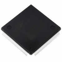
ST10F276Z5Q3TR STMicroelectronics, ST10F276Z5Q3TR Datasheet - Page 66

ST10F276Z5Q3TR
Manufacturer Part Number
ST10F276Z5Q3TR
Description
MCU 16BIT 832KBIT FLASH 144-PQFP
Manufacturer
STMicroelectronics
Series
ST10r
Datasheet
1.ST10F276Z5T3.pdf
(239 pages)
Specifications of ST10F276Z5Q3TR
Core Processor
ST10
Core Size
16-Bit
Speed
64MHz
Connectivity
ASC, CAN, EBI/EMI, I²C, SSC, UART/USART
Peripherals
POR, PWM, WDT
Number Of I /o
111
Program Memory Size
832KB (832K x 8)
Program Memory Type
FLASH
Ram Size
68K x 8
Voltage - Supply (vcc/vdd)
4.5 V ~ 5.5 V
Data Converters
A/D 24x10b
Oscillator Type
Internal
Operating Temperature
-40°C ~ 125°C
Package / Case
144-QFP
Processor Series
ST10F27x
Core
ST10
Data Bus Width
16 bit
Data Ram Size
68 KB
Interface Type
CAN, I2C
Maximum Clock Frequency
64 MHz
Number Of Programmable I/os
111
Number Of Timers
5
Maximum Operating Temperature
+ 125 C
Mounting Style
SMD/SMT
Minimum Operating Temperature
- 40 C
On-chip Adc
10 bit, 24 Channel
For Use With
497-6399 - KIT DEV STARTER ST10F276Z5
Lead Free Status / RoHS Status
Lead free / RoHS Compliant
Eeprom Size
-
Lead Free Status / Rohs Status
Details
Available stocks
Company
Part Number
Manufacturer
Quantity
Price
Company:
Part Number:
ST10F276Z5Q3TR
Manufacturer:
STMicroelectronics
Quantity:
10 000
- Current page: 66 of 239
- Download datasheet (3Mb)
Bootstrap loader
5.5.2
5.6
5.6.1
5.6.2
Note:
5.6.3
66/239
Hardware aspects
Although the new bootstrap loader is designed to be compatible with the old bootstrap
loader, there are a few hardware requirements for the new bootstrap loader as summarized
in
Table 35.
Alternate boot mode (ABM)
Activation
Alternate boot is activated with the combination ‘01’ on Port0L[5..4] at the rising edge of
RSTIN.
Memory mapping
The ST10F276Z5 has the same memory mapping for standard boot mode and for alternate
boot mode:
●
●
●
The alternate boot mode can be used to reprogram the whole content of the device User
Flash (except Block 0 in Bank 2, where the alternate boot is mapped into).
Interrupts
The ST10 interrupt vector table is always mapped from address 00’0000h.
As a consequence, interrupts are not allowed in Alternate Boot mode; all maskable and non
maskable interrupts must be disabled.
P4.5 can be used as output in
BSL mode.
Level on CAN1_RxD can
change during boot Step 2.
Table
Actual bootstrap loader
Test-Flash: Mapped from 00’0000h. The Standard Bootstrap Loader can be started by
executing a jump to the address of this routine (JMPS 00’xxxx; address to be defined).
User Flash: The User Flash is divided in two parts: The IFLASH, visible only for
memory reads and memory writes (no code fetch) and the XFLASH, visible for any
ST10 access (memory read, memory write and code fetch).
All device XRAM and Xperipherals modules can be accessed if enabled in XPERCON
register.
35.
Hardware topics summary
P4.5 cannot be used as user output
in BSL mode, but only as CAN1_RxD
or input or address segments.
Level on CAN1_RxD must be stable
at ‘1’ during boot Step 2.
New bootstrap loader
External pull-up on P4.5
needed.
Comments
ST10F276Z5
Related parts for ST10F276Z5Q3TR
Image
Part Number
Description
Manufacturer
Datasheet
Request
R

Part Number:
Description:
MCU 16BIT 832K FLASH 144-LQFP
Manufacturer:
STMicroelectronics
Datasheet:

Part Number:
Description:
MCU 16BIT 832K FLASH 144-LQFP
Manufacturer:
STMicroelectronics
Datasheet:

Part Number:
Description:
MCU 16BIT 832K FLASH 144-PQFP
Manufacturer:
STMicroelectronics
Datasheet:

Part Number:
Description:
MCU 16BIT 832K FLASH 144-PQFP
Manufacturer:
STMicroelectronics
Datasheet:

Part Number:
Description:
16-bit Microcontrollers - MCU 16-Bit MCU 832 kByte 68 KB RAM CMOS
Manufacturer:
STMicroelectronics

Part Number:
Description:
STMicroelectronics [RIPPLE-CARRY BINARY COUNTER/DIVIDERS]
Manufacturer:
STMicroelectronics
Datasheet:

Part Number:
Description:
STMicroelectronics [LIQUID-CRYSTAL DISPLAY DRIVERS]
Manufacturer:
STMicroelectronics
Datasheet:

Part Number:
Description:
BOARD EVAL FOR MEMS SENSORS
Manufacturer:
STMicroelectronics
Datasheet:

Part Number:
Description:
NPN TRANSISTOR POWER MODULE
Manufacturer:
STMicroelectronics
Datasheet:

Part Number:
Description:
TURBOSWITCH ULTRA-FAST HIGH VOLTAGE DIODE
Manufacturer:
STMicroelectronics
Datasheet:

Part Number:
Description:
Manufacturer:
STMicroelectronics
Datasheet:

Part Number:
Description:
DIODE / SCR MODULE
Manufacturer:
STMicroelectronics
Datasheet:


