MC908AZ60AVFUER Freescale Semiconductor, MC908AZ60AVFUER Datasheet - Page 145
MC908AZ60AVFUER
Manufacturer Part Number
MC908AZ60AVFUER
Description
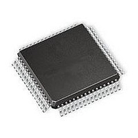
IC MCU 64K FLASH 8.4MHZ 64-QFP
Manufacturer
Freescale Semiconductor
Series
HC08r
Datasheet
1.MC908AZ60ACFUER.pdf
(414 pages)
Specifications of MC908AZ60AVFUER
Core Processor
HC08
Core Size
8-Bit
Speed
8.4MHz
Connectivity
CAN, SCI, SPI
Peripherals
LVD, POR, PWM
Number Of I /o
52
Program Memory Size
60KB (60K x 8)
Program Memory Type
FLASH
Eeprom Size
1K x 8
Ram Size
2K x 8
Voltage - Supply (vcc/vdd)
4.5 V ~ 5.5 V
Data Converters
A/D 15x8b
Oscillator Type
Internal
Operating Temperature
-40°C ~ 105°C
Package / Case
64-QFP
Processor Series
HC08AZ
Core
HC08
Data Bus Width
8 bit
Data Ram Size
2 KB
Interface Type
SCI, SPI
Maximum Clock Frequency
8.4 MHz
Number Of Programmable I/os
52
Number Of Timers
8
Maximum Operating Temperature
+ 105 C
Mounting Style
SMD/SMT
Development Tools By Supplier
FSICEBASE, M68CBL05CE, ZK-HC08AX-A, M68EM08AS/AZ60AE
Minimum Operating Temperature
- 40 C
On-chip Adc
8 bit, 15 Channel
Lead Free Status / RoHS Status
Lead free / RoHS Compliant
Available stocks
Company
Part Number
Manufacturer
Quantity
Price
Company:

Part Number:
MC908AZ60AVFUER
Manufacturer:
Freescale Semiconductor
Quantity:
10 000


Chapter 11
Configuration Register (CONFIG-1)
11.1 Introduction
This chapter describes the configuration register (CONFIG-1), which contains bits that configure these
options:
11.2 Functional Description
The configuration register is a write-once register. Out of reset, the configuration register will read the
default value. Once the register is written, further writes will have no effect until a reset occurs.
LVISTOP — LVI Stop Mode Enable Bit
Freescale Semiconductor
•
•
•
•
•
•
LVISTOP enables the LVI module in stop mode. (See
1 = LVI enabled during stop mode
0 = LVI disabled during stop mode
Resets caused by the LVI module
Power to the LVI module
LVI enabled during stop mode
Stop mode recovery time (32 CGMXCLK cycles or 4096 CGMXCLK cycles)
Computer operating properly module (COP)
Stop instruction enable/disable.
Address:
If the LVI module and the LVI reset signal are enabled, a reset occurs when
V
least nine consecutive CPU cycles. Once an LVI reset occurs, the MCU
remains in reset until V
To have the LVI enabled in stop mode, the LVIPWR must be at a logic 1
and the LVISTOP bit must be at a logic 1. Take note that by enabling the
LVI in stop mode, the stop I
Reset:
Read:
Write:
DD
MC68HC908AZ60A • MC68HC908AS60A • MC68HC908AS60E Data Sheet, Rev. 6
falls to a voltage, LVI
LVISTOP
$001F
Bit 7
R
0
Figure 11-1. Configuration Register (CONFIG-1)
= Reserved
R
6
1
DD
LVIRST
TRIPF
rises to a voltage, LVI
DD
5
1
current will be higher.
, and remains at or below that level for at
NOTE
NOTE
LVIPWR
4
1
Chapter 16 Low-Voltage Inhibit
SSREC
3
0
TRIPR
COPL
.
2
0
STOP
1
0
COPD
Bit 0
0
(LVI)).
145
Related parts for MC908AZ60AVFUER
Image
Part Number
Description
Manufacturer
Datasheet
Request
R

Part Number:
Description:
Manufacturer:
Freescale Semiconductor, Inc
Datasheet:
Part Number:
Description:
Manufacturer:
Freescale Semiconductor, Inc
Datasheet:
Part Number:
Description:
Manufacturer:
Freescale Semiconductor, Inc
Datasheet:
Part Number:
Description:
Manufacturer:
Freescale Semiconductor, Inc
Datasheet:
Part Number:
Description:
Manufacturer:
Freescale Semiconductor, Inc
Datasheet:
Part Number:
Description:
Manufacturer:
Freescale Semiconductor, Inc
Datasheet:
Part Number:
Description:
Manufacturer:
Freescale Semiconductor, Inc
Datasheet:
Part Number:
Description:
Manufacturer:
Freescale Semiconductor, Inc
Datasheet:
Part Number:
Description:
Manufacturer:
Freescale Semiconductor, Inc
Datasheet:
Part Number:
Description:
Manufacturer:
Freescale Semiconductor, Inc
Datasheet:
Part Number:
Description:
Manufacturer:
Freescale Semiconductor, Inc
Datasheet:
Part Number:
Description:
Manufacturer:
Freescale Semiconductor, Inc
Datasheet:
Part Number:
Description:
Manufacturer:
Freescale Semiconductor, Inc
Datasheet:
Part Number:
Description:
Manufacturer:
Freescale Semiconductor, Inc
Datasheet:
Part Number:
Description:
Manufacturer:
Freescale Semiconductor, Inc
Datasheet: