HD6417034AFI20V Renesas Electronics America, HD6417034AFI20V Datasheet - Page 109
HD6417034AFI20V
Manufacturer Part Number
HD6417034AFI20V
Description
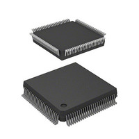
MCU 5V 0K I-TEMP PB-FREE 112-QFP
Manufacturer
Renesas Electronics America
Series
SuperH® SH7030r
Datasheet
1.HD6417034AFI20.pdf
(689 pages)
Specifications of HD6417034AFI20V
Core Processor
SH-1
Core Size
32-Bit
Speed
20MHz
Connectivity
EBI/EMI, SCI
Peripherals
DMA, POR, PWM, WDT
Number Of I /o
32
Program Memory Type
ROMless
Ram Size
4K x 8
Voltage - Supply (vcc/vdd)
4.5 V ~ 5.5 V
Data Converters
A/D 8x10b
Oscillator Type
Internal
Operating Temperature
-20°C ~ 75°C
Package / Case
112-QFP
Lead Free Status / RoHS Status
Lead free / RoHS Compliant
Eeprom Size
-
Program Memory Size
-
Available stocks
Company
Part Number
Manufacturer
Quantity
Price
Company:

Part Number:
HD6417034AFI20V
Manufacturer:
Renesas Electronics America
Quantity:
10 000


5.6
When the following operations are performed in the order shown when a pin to which IRQ input is
assigned is designated as a general input pin by the pin function controller (PFC) and inputs a low-
level signal, the IRQ falling edge is detected, and an interrupt request is detected, immediately
after the setting in (b) is performed:
Therefore, when switching the pin function from general input pin to IRQ input, the pin function
controller (PFC) setting should be changed to IRQ input while the pin to which IRQ input is
assigned is high.
An interrupt control register (ICR) setting is made so that an interrupt is detected at the falling
edge of IRQ. …(a)
The function of pins to which IRQ input is assigned is switched from general input to IRQ
input by a pin function controller (PFC) setting.
Instruction (instruction replaced by
F (Instruction fetch)
D (Instruction decoding)
E (Instruction execution)
M (Memory access)
Note: For the interrupt acceptance timing, see table 4.1, Exception Source Detection and
Usage Notes
interrupt exception handling)
Interrupt service routine—
Start of Handling, in section 4.1.2, Exception Handling Operation.
Figure 5.4 Example of Pipelining in IRQ Interrupt Acceptance
first instruction
Overrun fetch
When m1 = m2 = m3, the interrupt response time is 11 cycles.
IRQ
IRQOUT
Instruction fetched from memory where program is stored.
The fetched instruction is decoded.
Data operations and address calculations are performed
according to the decoded results.
Data in memory is accessed.
Interrupt accepted
(edge)
(level)
3
F D
F
E E
3
5 + m1 + m2 + m3
…(b)
Rev. 7.00 Jan 31, 2006 page 81 of 658
m1 m2 1 m3 1
M M E
Section 5 Interrupt Controller (INTC)
M E E
F D E
REJ09B0272-0700
Related parts for HD6417034AFI20V
Image
Part Number
Description
Manufacturer
Datasheet
Request
R

Part Number:
Description:
KIT STARTER FOR M16C/29
Manufacturer:
Renesas Electronics America
Datasheet:

Part Number:
Description:
KIT STARTER FOR R8C/2D
Manufacturer:
Renesas Electronics America
Datasheet:

Part Number:
Description:
R0K33062P STARTER KIT
Manufacturer:
Renesas Electronics America
Datasheet:

Part Number:
Description:
KIT STARTER FOR R8C/23 E8A
Manufacturer:
Renesas Electronics America
Datasheet:

Part Number:
Description:
KIT STARTER FOR R8C/25
Manufacturer:
Renesas Electronics America
Datasheet:

Part Number:
Description:
KIT STARTER H8S2456 SHARPE DSPLY
Manufacturer:
Renesas Electronics America
Datasheet:

Part Number:
Description:
KIT STARTER FOR R8C38C
Manufacturer:
Renesas Electronics America
Datasheet:

Part Number:
Description:
KIT STARTER FOR R8C35C
Manufacturer:
Renesas Electronics America
Datasheet:

Part Number:
Description:
KIT STARTER FOR R8CL3AC+LCD APPS
Manufacturer:
Renesas Electronics America
Datasheet:
Part Number:
Description:
KIT STARTER FOR RX610
Manufacturer:
Renesas Electronics America
Datasheet:

Part Number:
Description:
KIT STARTER FOR R32C/118
Manufacturer:
Renesas Electronics America
Datasheet:

Part Number:
Description:
KIT DEV RSK-R8C/26-29
Manufacturer:
Renesas Electronics America
Datasheet:

Part Number:
Description:
KIT STARTER FOR SH7124
Manufacturer:
Renesas Electronics America
Datasheet:

Part Number:
Description:
KIT STARTER FOR H8SX/1622
Manufacturer:
Renesas Electronics America
Datasheet:

Part Number:
Description:
KIT DEV FOR SH7203
Manufacturer:
Renesas Electronics America
Datasheet: