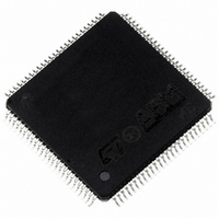
ST92F250CV2TB STMicroelectronics, ST92F250CV2TB Datasheet - Page 327

ST92F250CV2TB
Manufacturer Part Number
ST92F250CV2TB
Description
IC MCU 256K FLASH 100-TQFP
Manufacturer
STMicroelectronics
Series
ST9r
Datasheet
1.ST92F150CV1TB.pdf
(429 pages)
Specifications of ST92F250CV2TB
Core Processor
ST9
Core Size
8/16-Bit
Speed
24MHz
Connectivity
CAN, I²C, LIN, SCI, SPI
Peripherals
DMA, LVD, POR, PWM, WDT
Number Of I /o
80
Program Memory Size
256KB (256K x 8)
Program Memory Type
FLASH
Eeprom Size
1K x 8
Ram Size
8K x 8
Voltage - Supply (vcc/vdd)
4.5 V ~ 5.5 V
Data Converters
A/D 16x10b
Oscillator Type
Internal
Operating Temperature
-40°C ~ 105°C
Package / Case
100-TQFP, 100-VQFP
Processor Series
ST92F25x
Core
ST9
Data Bus Width
8 bit, 16 bit
Data Ram Size
8 KB
Interface Type
CAN, I2C, SCI, SPI
Maximum Clock Frequency
24 MHz
Number Of Programmable I/os
80
Number Of Timers
5 x 16 bit
Operating Supply Voltage
4.5 V to 5.5 V
Maximum Operating Temperature
+ 105 C
Mounting Style
SMD/SMT
Development Tools By Supplier
ST92F150-EPB
Minimum Operating Temperature
- 40 C
On-chip Adc
16 bit x 10 bit
Lead Free Status / RoHS Status
Lead free / RoHS Compliant
Other names
497-2140
Available stocks
Company
Part Number
Manufacturer
Quantity
Price
- Current page: 327 of 429
- Download datasheet (8Mb)
CONTROLLER AREA NETWORK (Cont’d)
Figure 144. bxCAN Operating Modes
10.10.4 Operating Modes
bxCAN has three main operating modes: initiali-
zation, normal and sleep. After a hardware reset,
bxCAN is in sleep mode to reduce power con-
sumption and an internal pull-up is active on RX1.
The software requests bxCAN to enter initializa-
tion or sleep mode by setting the INRQ or SLEEP
bits in the CMCR register. Once the mode has
been entered, bxCAN confirms it by setting the
INAK or SLAK bits in the CMSR register and the
internal pull-up is disabled. When neither INAK nor
SLAK are set, bxCAN is in normal mode. Before
entering normal mode bxCAN always has to syn-
chronize on the CAN bus. To synchronize, bx-
CAN waits until the CAN bus is idle, this means 11
consecutive recessive bits have been monitored
on CANRX.
10.10.4.1 Initialization Mode
The software initialization can be done while the
hardware is in Initialization mode. To enter this
mode the software sets the INRQ bit in the CMCR
register and waits until the hardware has con-
firmed the request by setting the INAK bit in the
CMSR register.
To leave Initialization mode, the software clears
the INQR bit. bxCAN has left Initialization mode
once the INAK bit has been cleared by hardware.
While in Initialization Mode, all message transfers
to and from the CAN bus are stopped and the sta-
NORMAL
SLAK= 0
INAK = 0
SLEEP
RESET
SLAK= 1
INAK = 0
INRQ
SLAK= X
INAK = X
SYNC
CONTROLLER AREA NETWORK (bxCAN)
tus of the CAN bus output CANTX is recessive
(high).
Entering Initialization Mode does not change any
of the configuration registers.
To initialize the CAN Controller, software has to
set up the Bit Timing registers and the filters. If a
filter bank is not used, it is recommended to leave
it non active (leave the corresponding FACT bit
cleared).
10.10.4.2 Normal Mode
Once the initialization has been done, the software
must request the hardware to enter Normal mode,
to synchronize on the CAN bus and start reception
and transmission. Entering Normal mode is done
by clearing the INRQ bit in the CMCR register and
waiting until the hardware has confirmed the re-
quest by clearing the INAK bit in the CMSR regis-
ter. Afterwards, the bxCAN synchronizes with the
data transfer on the CAN bus by waiting for the oc-
currence of a sequence of 11 consecutive reces-
sive bits (≡ Bus Idle) before it can take part in bus
activities and start message transfer.
The initialization of the filter values is independent
from Initialization Mode but must be done while the
filter is not active (corresponding FACTx bit
cleared). The filter scale and mode configuration
must be configured before entering Normal Mode.
INITIALIZATION
SLAK= 0
INAK = 1
327/429
9
Related parts for ST92F250CV2TB
Image
Part Number
Description
Manufacturer
Datasheet
Request
R

Part Number:
Description:
STMicroelectronics [RIPPLE-CARRY BINARY COUNTER/DIVIDERS]
Manufacturer:
STMicroelectronics
Datasheet:

Part Number:
Description:
STMicroelectronics [LIQUID-CRYSTAL DISPLAY DRIVERS]
Manufacturer:
STMicroelectronics
Datasheet:

Part Number:
Description:
BOARD EVAL FOR MEMS SENSORS
Manufacturer:
STMicroelectronics
Datasheet:

Part Number:
Description:
NPN TRANSISTOR POWER MODULE
Manufacturer:
STMicroelectronics
Datasheet:

Part Number:
Description:
TURBOSWITCH ULTRA-FAST HIGH VOLTAGE DIODE
Manufacturer:
STMicroelectronics
Datasheet:

Part Number:
Description:
Manufacturer:
STMicroelectronics
Datasheet:

Part Number:
Description:
DIODE / SCR MODULE
Manufacturer:
STMicroelectronics
Datasheet:

Part Number:
Description:
DIODE / SCR MODULE
Manufacturer:
STMicroelectronics
Datasheet:

Part Number:
Description:
Search -----> STE16N100
Manufacturer:
STMicroelectronics
Datasheet:

Part Number:
Description:
Search ---> STE53NA50
Manufacturer:
STMicroelectronics
Datasheet:

Part Number:
Description:
NPN Transistor Power Module
Manufacturer:
STMicroelectronics
Datasheet:

Part Number:
Description:
DIODE / SCR MODULE
Manufacturer:
STMicroelectronics
Datasheet:


