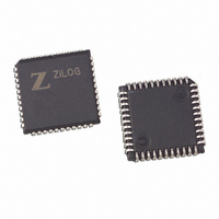
Z8F3201VN020EC00TR Zilog, Z8F3201VN020EC00TR Datasheet - Page 47

Z8F3201VN020EC00TR
Manufacturer Part Number
Z8F3201VN020EC00TR
Description
IC ENCORE MCU FLASH 32K 44PLCC
Manufacturer
Zilog
Series
Encore!®r
Datasheet
1.Z8F1601VN020EC.pdf
(246 pages)
Specifications of Z8F3201VN020EC00TR
Core Processor
Z8
Core Size
8-Bit
Speed
20MHz
Connectivity
I²C, IrDA, SPI, UART/USART
Peripherals
Brown-out Detect/Reset, DMA, POR, PWM, WDT
Number Of I /o
31
Program Memory Size
32KB (32K x 8)
Program Memory Type
FLASH
Ram Size
2K x 8
Voltage - Supply (vcc/vdd)
3 V ~ 3.6 V
Data Converters
A/D 8x10b
Oscillator Type
Internal
Operating Temperature
-40°C ~ 105°C
Package / Case
44-LCC (J-Lead)
Lead Free Status / RoHS Status
Contains lead / RoHS non-compliant
Eeprom Size
-
Other names
Z8F3201VN020EC00T
Available stocks
Company
Part Number
Manufacturer
Quantity
Price
- Current page: 47 of 246
- Download datasheet (2Mb)
Stop Mode Recovery
Table 9. Stop Mode Recovery Sources and Resulting Action
PS017610-0404
Operating Mode
Stop mode
External Pin Reset
Stop Mode Recovery Using Watch-Dog Timer Time-Out
The RESET pin has a Schmitt-triggered input and an internal pull-up. Once the RESET
pin is asserted, the device progresses through the Short Reset sequence. While the RESET
input pin is asserted Low, the Z8F640x family device continues to be held in the Reset
state. If the RESET pin is held Low beyond the Short Reset time-out, the device exits the
Reset state immediately following RESET pin deassertion. Following a Short Reset initi-
ated by the external RESET pin, the EXT status bit in the Watch-Dog Timer Control
(WDTCTL) register is set to 1.
Stop mode is entered by execution of a
Low-Power Modes chapter for detailed Stop mode information. During Stop Mode
Recovery, the Z8F640x family device is held in reset for 514 cycles of the Watch-Dog
Timer oscillator followed by 16 cycles of the system clock (crystal oscillator). Stop Mode
Recovery does not affect any values in the Register File, including the Stack Pointer, Reg-
ister Pointer, Flags and general-purpose RAM.
The eZ8 CPU fetches the Reset vector at Program Memory addresses
and loads that value into the Program Counter. Program execution begins at the Reset vec-
tor address. Following Stop Mode Recovery, the STOP bit in the Watch-Dog Timer Con-
trol Register is set to 1. Table 9 lists the Stop Mode Recovery sources and resulting
actions. The text following provides more detailed information on each of the Stop Mode
Recovery sources.
If the Watch-Dog Timer times out during Stop mode, the Z8F640x family device under-
goes a STOP Mode Recovery sequence. In the Watch-Dog Timer Control register, the
WDT and STOP bits are set to 1. If the Watch-Dog Timer is configured to generate an inter-
rupt upon time-out and the device is configured to respond to interrupts, the Z8F640x fam-
ily device services the Watch-Dog Timer interrupt request following the normal Stop
Mode Recovery sequence.
Stop Mode Recovery Source
Watch-Dog Timer time-out
when configured for Reset
Watch-Dog Timer time-out
when configured for interrupt
Data transition on any GPIO Port pin
enabled as a Stop Mode Recovery source
Z8F640x/Z8F480x/Z8F320x/Z8F240x/Z8F160x
STOP
instruction by the eZ8 CPU. Refer to the
Action
Stop Mode Recovery
Stop Mode Recovery followed by interrupt (if
interrupts are enabled)
Stop Mode Recovery
Reset and Stop Mode Recovery
0002H
Z8 Encore!
and
0003H
®
29
Related parts for Z8F3201VN020EC00TR
Image
Part Number
Description
Manufacturer
Datasheet
Request
R

Part Number:
Description:
Communication Controllers, ZILOG INTELLIGENT PERIPHERAL CONTROLLER (ZIP)
Manufacturer:
Zilog, Inc.
Datasheet:

Part Number:
Description:
KIT DEV FOR Z8 ENCORE 16K TO 64K
Manufacturer:
Zilog
Datasheet:

Part Number:
Description:
KIT DEV Z8 ENCORE XP 28-PIN
Manufacturer:
Zilog
Datasheet:

Part Number:
Description:
DEV KIT FOR Z8 ENCORE 8K/4K
Manufacturer:
Zilog
Datasheet:

Part Number:
Description:
KIT DEV Z8 ENCORE XP 28-PIN
Manufacturer:
Zilog
Datasheet:

Part Number:
Description:
DEV KIT FOR Z8 ENCORE 4K TO 8K
Manufacturer:
Zilog
Datasheet:

Part Number:
Description:
CMOS Z8 microcontroller. ROM 16 Kbytes, RAM 256 bytes, speed 16 MHz, 32 lines I/O, 3.0V to 5.5V
Manufacturer:
Zilog, Inc.
Datasheet:

Part Number:
Description:
Low-cost microcontroller. 512 bytes ROM, 61 bytes RAM, 8 MHz
Manufacturer:
Zilog, Inc.
Datasheet:

Part Number:
Description:
Z8 4K OTP Microcontroller
Manufacturer:
Zilog, Inc.
Datasheet:

Part Number:
Description:
CMOS SUPER8 ROMLESS MCU
Manufacturer:
Zilog, Inc.
Datasheet:

Part Number:
Description:
SL1866 CMOSZ8 OTP Microcontroller
Manufacturer:
Zilog, Inc.
Datasheet:

Part Number:
Description:
SL1866 CMOSZ8 OTP Microcontroller
Manufacturer:
Zilog, Inc.
Datasheet:

Part Number:
Description:
OTP (KB) = 1, RAM = 125, Speed = 12, I/O = 14, 8-bit Timers = 2, Comm Interfaces Other Features = Por, LV Protect, Voltage = 4.5-5.5V
Manufacturer:
Zilog, Inc.
Datasheet:

Part Number:
Description:
Manufacturer:
Zilog, Inc.
Datasheet:


