HD64F3694FY Renesas Electronics America, HD64F3694FY Datasheet - Page 264
HD64F3694FY
Manufacturer Part Number
HD64F3694FY
Description
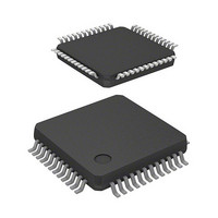
IC H8 MCU FLASH 32K 48-LQFP
Manufacturer
Renesas Electronics America
Series
H8® H8/300H Tinyr
Datasheet
1.HD64F3694GFYV.pdf
(452 pages)
Specifications of HD64F3694FY
Core Processor
H8/300H
Core Size
16-Bit
Speed
20MHz
Connectivity
I²C, SCI
Peripherals
PWM, WDT
Number Of I /o
29
Program Memory Size
32KB (32K x 8)
Program Memory Type
FLASH
Ram Size
2K x 8
Voltage - Supply (vcc/vdd)
3 V ~ 5.5 V
Data Converters
A/D 8x10b
Oscillator Type
Internal
Operating Temperature
-20°C ~ 75°C
Package / Case
48-LQFP
Lead Free Status / RoHS Status
Contains lead / RoHS non-compliant
Eeprom Size
-
Available stocks
Company
Part Number
Manufacturer
Quantity
Price

Part Number:
HD64F3694FYJV
Manufacturer:
RENESAS/瑞萨
Quantity:
20 000
Company:
Part Number:
HD64F3694FYV
Manufacturer:
Renesas Electronics America
Quantity:
10 000


Section 15 I
15.3.1
ICCR1 enables or disables the I
master or slave mode, transmission or reception, and transfer clock frequency in master mode.
Rev.5.00 Nov. 02, 2005 Page 234 of 418
REJ09B0028-0500
Bit
7
6
5
4
I
I
I
2
2
2
C bus transmit data register (ICDRT)
C bus receive data register (ICDRR)
C bus shift register (ICDRS)
Bit Name
ICE
RCVD
MST
TRS
I
2
2
C Bus Control Register 1 (ICCR1)
C Bus Interface 2 (IIC2)
Initial
Value
0
0
0
0
2
R/W
R/W
R/W
R/W
R/W
C bus interface 2, controls transmission or reception, and selects
Description
I
0: This module is halted. (SCL and SDA pins are set to port
1: This bit is enabled for transfer operations. (SCL and SDA
Reception Disable
This bit enables or disables the next operation when TRS is
0 and ICDRR is read.
0: Enables next reception
1: Disables next reception
Master/Slave Select
Transmit/Receive Select
In master mode with the I
lost, MST and TRS are both reset by hardware, causing a
transition to slave receive mode. Modification of the TRS bit
should be made between transfer frames.
After data receive has been started in slave receive mode,
when the first seven bits of the receive data agree with the
slave address that is set to SAR and the eighth bit is 1,
TRS is automatically set to 1. If an overrun error occurs in
master mode with the clock synchronous serial format,
MST is cleared to 0 and slave receive mode is entered.
Operating modes are described below according to MST
and TRS combination. When clocked synchronous serial
format is selected and MST is 1, clock is output.
00: Slave receive mode
01: Slave transmit mode
10: Master receive mode
11: Master transmit mode
2
C Bus Interface Enable
function.)
pins are bus drive state.)
2
C bus format, when arbitration is
Related parts for HD64F3694FY
Image
Part Number
Description
Manufacturer
Datasheet
Request
R

Part Number:
Description:
(HD64 Series) Hitachi Single-Chip Microcomputer
Manufacturer:
Hitachi Semiconductor
Datasheet:

Part Number:
Description:
KIT STARTER FOR M16C/29
Manufacturer:
Renesas Electronics America
Datasheet:

Part Number:
Description:
KIT STARTER FOR R8C/2D
Manufacturer:
Renesas Electronics America
Datasheet:

Part Number:
Description:
R0K33062P STARTER KIT
Manufacturer:
Renesas Electronics America
Datasheet:

Part Number:
Description:
KIT STARTER FOR R8C/23 E8A
Manufacturer:
Renesas Electronics America
Datasheet:

Part Number:
Description:
KIT STARTER FOR R8C/25
Manufacturer:
Renesas Electronics America
Datasheet:

Part Number:
Description:
KIT STARTER H8S2456 SHARPE DSPLY
Manufacturer:
Renesas Electronics America
Datasheet:

Part Number:
Description:
KIT STARTER FOR R8C38C
Manufacturer:
Renesas Electronics America
Datasheet:

Part Number:
Description:
KIT STARTER FOR R8C35C
Manufacturer:
Renesas Electronics America
Datasheet:

Part Number:
Description:
KIT STARTER FOR R8CL3AC+LCD APPS
Manufacturer:
Renesas Electronics America
Datasheet:
Part Number:
Description:
KIT STARTER FOR RX610
Manufacturer:
Renesas Electronics America
Datasheet:

Part Number:
Description:
KIT STARTER FOR R32C/118
Manufacturer:
Renesas Electronics America
Datasheet:

Part Number:
Description:
KIT DEV RSK-R8C/26-29
Manufacturer:
Renesas Electronics America
Datasheet:

Part Number:
Description:
KIT STARTER FOR SH7124
Manufacturer:
Renesas Electronics America
Datasheet:

Part Number:
Description:
KIT STARTER FOR H8SX/1622
Manufacturer:
Renesas Electronics America
Datasheet: