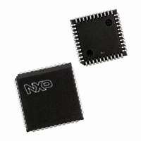
SC28L91A1A,512 NXP Semiconductors, SC28L91A1A,512 Datasheet - Page 2

SC28L91A1A,512
Manufacturer Part Number
SC28L91A1A,512
Description
IC UART SINGLE W/FIFO 44-PLCC
Manufacturer
NXP Semiconductors
Series
IMPACTr
Datasheet
1.SC28L91A1A529.pdf
(43 pages)
Specifications of SC28L91A1A,512
Features
False-start Bit Detection
Number Of Channels
1, UART
Fifo's
16 Byte
Voltage - Supply
3.3V, 5V
With Auto Flow Control
Yes
With False Start Bit Detection
Yes
With Modem Control
Yes
With Cmos
Yes
Mounting Type
Surface Mount
Package / Case
44-PLCC
Voltage
3 V ~ 3.6 V, 4.5 V ~ 5.5 V
Lead Free Status / RoHS Status
Lead free / RoHS Compliant
Other names
935267418512
SC28L91A1A
SC28L91A1A
SC28L91A1A
SC28L91A1A
Available stocks
Company
Part Number
Manufacturer
Quantity
Price
Company:
Part Number:
SC28L91A1A,512
Manufacturer:
NXP Semiconductors
Quantity:
10 000
rates; a 16X clock derived from a programmable counter/timer, or an
external 1X or 16X clock. The baud rate generator and counter/timer
DESCRIPTION
The SC28L91 is a new member of the IMPACT family of Serial
Communications Controllers. It is a single channel UART operating
at 3.3 V and 5.0 V V
with software of the SC28L92 and previous UARTs offered by
Philips. It is a new part that is similar to our previous one channel
part but is vastly improved. The improvements being: 16 character
receiver, 16 character transmit FIFOs, watch dog timer for the
receiver, mode register 0 is added, extended baud rate, over all
faster bus and data speeds, programmable receiver and transmitter
interrupts and versatile I/O structure. (The previous one channel
part, SCC2691, is NOT being discontinued.)
Pin programming will allow the device to operate with either the
Motorola or Intel bus interface. Bit 3 of the MR0 register allows the
device to operate in an 8-byte FIFO mode if strict compliance with
an 8-byte FIFO structure is required.
The Philips Semiconductors SC28L91 Universal Asynchronous
Receiver/Transmitter (UART) is a single-chip CMOS-LSI
communications device that provides a full-duplex asynchronous
receiver/transmitter channel in a single package. It interfaces
directly with microprocessors and may be used in a polled or
interrupt driven system with modem and DMA interface.
The operating mode and data format of the channel can be
programmed independently. Additionally, the receiver and
transmitter can select its operating speed as one of 28 fixed baud
can operate directly from a crystal or from external clock inputs. The
ability to independently program the operating speed of the receiver
and transmitter make the UART particularly attractive for dual-speed
channel applications such as clustered terminal systems.
The receiver and transmitter is buffered by 8 or 16 character FIFOs
to minimize the potential of receiver overrun, transmitter underrun
and to reduce interrupt overhead in interrupt driven systems. In
addition, a flow control capability is provided via RTS/CTS signaling
to disable a remote transmitter when the receiver buffer is full.
DMA interface is and other general purpose signals are provided on
the SC28L91 via a multipurpose 7-bit input port and a multipurpose
8-bit output port. These can be used as general-purpose ports or
can be assigned specific functions (such as clock inputs or
status/interrupt outputs, FIFO conditions) under program control.
The SC28L91 is available in two package versions: a 44-pin PLCC
and 44-pin plastic quad flat pack (PQFP).
FEATURES
Philips Semiconductors
2004 Oct 21
Member of IMPACT family: 3.3 to 5.0 volt , –40 C to +85 C and
68K for 80xxx bus interface for all devices.
A full-duplex independent asynchronous receiver/transmitter
16 character FIFOs for each receiver and transmitter
Pin programming selects 68K or 80xxx-bus interface
Programmable data format
– 5 to 8 data bits plus parity
– Odd, even, no parity or force parity
– – 1, 1.5 or 2 stop bits programmable in 1/16-bit increments
3.3 V or 5.0 V Universal Asynchronous
Receiver/Transmitter (UART)
CC
, 8 or 16 byte FIFOs and is quite compatible
2
–
– Each FIFO can be programmed for four different interrupt levels
16-bit programmable Counter/Timer
Programmable baud rate for each receiver and transmitter
selectable from:
– 28 fixed rates: 50 to 230.4 k baud
– Other baud rates to 1 MHz at 16X
– External 1X or 16X clock
Parity, framing, and overrun error detection
False start bit detection
Line break detection and generation
Programmable channel mode
– Normal (full-duplex)
– Automatic echo
– Local loop back
– Remote loop back
– Multi-drop mode (also called ‘wake-up’ or ‘9-bit’)
Multi-function 7-bit input port (includes IACKN)
– Can serve as clock or control inputs
– Change of state detection on four inputs
– Inputs have typically >100 k pull-up resistors
– Change of state detectors for modem control
Multi-function 8-bit output port
– Individual bit set/reset capability
– Outputs can be programmed to be status/interrupt signals
– FIFO status for DMA interface
Versatile interrupt system
– Single interrupt output with eight maskable interrupting
– Output port can be configured to provide a total of up to six
– Watchdog timer for the receiver
Maximum data transfer rates:
1X – 1 Mbit/s, 16X – 1 Mbit/s
Automatic wake-up mode for multi-drop applications
Start-end break interrupt/status with mid-character break detect.
On-chip crystal oscillator
Power-down mode
Receiver time-out mode
Single +3.3 V or +5 V power supply
Programmable user-defined rates derived from a programmable
counter/timer
conditions
separate interrupt outputs that may be wire ORed.
Product data sheet
SC28L91


