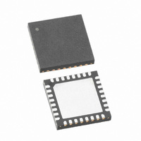
SX1212IWLTRT Semtech, SX1212IWLTRT Datasheet - Page 14

SX1212IWLTRT
Manufacturer Part Number
SX1212IWLTRT
Description
IC TXRX 300MHZ-510MHZ 32-TQFN
Manufacturer
Semtech
Datasheet
1.SX1212IWLTRT.pdf
(77 pages)
Specifications of SX1212IWLTRT
Frequency
300MHz ~ 510MHz
Data Rate - Maximum
150kbps
Modulation Or Protocol
FSK, OOK
Applications
AMR, ISM, Home Automation, Process Control
Power - Output
12.5dBm
Sensitivity
-110dBm
Voltage - Supply
2.1 V ~ 3.6 V
Current - Receiving
3mA
Current - Transmitting
25mA
Data Interface
PCB, Surface Mount
Antenna Connector
PCB, Surface Mount
Operating Temperature
-40°C ~ 85°C
Package / Case
32-TQFN
Operating Temperature (min)
-40C
Operating Temperature (max)
85C
Operating Temperature Classification
Industrial
Modulation Type
FSK/OOK
Package Type
TQFN EP
Operating Supply Voltage (min)
2.1V
Operating Supply Voltage (typ)
2.5/3.3V
Operating Supply Voltage (max)
3.6V
Lead Free Status / RoHS Status
Lead free / RoHS Compliant
Memory Size
-
Lead Free Status / Rohs Status
Supplier Unconfirmed
Other names
SX1212IWLTR
Available stocks
Company
Part Number
Manufacturer
Quantity
Price
Part Number:
SX1212IWLTRT
Manufacturer:
SEMTECH/美国升特
Quantity:
20 000
The crystal oscillator (XO) forms the reference oscillator of an Integer-N Phase Locked Loop (PLL), whose
operation is discussed in the following section. Figure 5 shows a block schematic of the SX1212 PLL. Here the
crystal reference frequency and the software controlled dividers R, P and S determine the output frequency of the
PLL.
The VCO tank inductors are connected on an external differential input. Similarly, the loop filter is also located
externally. However, there is an internal 8pF capacitance at VCO input that should be subtracted from the desired
loop filter capacitance.
The output signal of the VCO is used as the input to the local oscillator (LO) generator stage, illustrated in Figure 6.
The VCO frequency is subdivided and used in a series of up (down) conversions for transmission (reception).
With an integer-N PLL architecture, the following criterion must be met to ensure correct operation:
Rev 2 – June 18th, 2009
ADVANCED COMMUNICATIONS & SENSING
The comparison frequency, Fcomp, of the Phase Frequency Detector (PFD) input must remain higher than six
times the PLL bandwidth (PLLBW) to guarantee loop stability and to reject harmonics of the comparison
frequency Fcomp. This is expressed in the inequality:
However the PLLBW has to be sufficiently high to allow adequate PLL lock times
Because the divider ration R determines Fcomp, it should be set close to 119, leading to Fcomp≈100 kHz
which will ensure suitable PLL stability and speed.
3.2.3. PLL Architecture
3.2.4. PLL Tradeoffs
XT_M
VCO Output
XO
LO
XT_P
Figure 5: Frequency Synthesizer Description
÷(R
i
+1)
÷8
÷8
Fcomp
Figure 6: LO Generator
PLLBW ≤
PFD
Page 14 of 77
Fcomp
90°
90°
90°
6
÷75.(P
LF_M
i
+1)+S
Vtune
Q
Q
I
I
Q
I
i
LO1 Rx
LO2 Rx
LO1 Tx
LO2 Tx
LF_P
VCO_M
Receiver
LOs
Transmitter
LOs
VCO_P
VR_VCO
LO
www.semtech.com
SX1212


