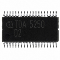
TDA5250 Infineon Technologies, TDA5250 Datasheet - Page 73

TDA5250
Manufacturer Part Number
TDA5250
Description
TX/RX ASK/FSK 868-870MHZ 38TSSOP
Manufacturer
Infineon Technologies
Type
Transceiverr
Specifications of TDA5250
Package / Case
38-TSSOP
Frequency
868MHz
Data Rate - Maximum
64kbps
Modulation Or Protocol
ASK, FSK
Applications
RKE, Remote Control Systems
Power - Output
9dBm
Sensitivity
-109dBm
Voltage - Supply
2.1 V ~ 5.5 V
Current - Receiving
9mA
Current - Transmitting
12mA
Data Interface
PCB, Surface Mount
Antenna Connector
PCB, Surface Mount
Operating Temperature
-40°C ~ 85°C
Operating Frequency
870 MHz
Operating Supply Voltage
2.5 V, 3.3 V, 5 V
Maximum Operating Temperature
+ 85 C
Minimum Operating Temperature
- 40 C
Mounting Style
SMD/SMT
Operating Temperature (min)
-40C
Operating Temperature (max)
85C
Operating Temperature Classification
Industrial
Product Depth (mm)
4.4mm
Product Length (mm)
9.7mm
Operating Supply Voltage (min)
2.1V
Operating Supply Voltage (max)
5.5V
Lead Free Status / RoHS Status
Lead free / RoHS Compliant
Memory Size
-
Lead Free Status / Rohs Status
Compliant
Other names
SP000012956
TDA5250
TDA5250INTR
TDA5250XT
TDA5250XT
TDA5250
TDA5250INTR
TDA5250XT
TDA5250XT
Available stocks
Company
Part Number
Manufacturer
Quantity
Price
Company:
Part Number:
TDA5250
Manufacturer:
Infineon Technologies
Quantity:
135
Company:
Part Number:
TDA5250D2
Manufacturer:
INFINEON
Quantity:
300
Part Number:
TDA5250D2
Manufacturer:
INFINEON/英飞凌
Quantity:
20 000
This gives 15ms ON time of a total period of 150ms which results in max. 0.9mA mean current
consumption in Self Polling Mode. The resulting worst case timing is shown in the following figure:
Figure 3-35
Description:
Assumption: the ON time comes right after the first frame (Case A). If OFF time is 135ms the
receiver turns on during Sync-pulses and the PwdDD- pulse wakes up the µP.
If the ON time is in the center of the 50ms gap of transmission (Case B), the Data Detect Logic will
wake up the µP 135ms later.
If ON time is over just before Sync-pulses (Case C), next ON time is during Data transmission and
Data Detect Logic will trigger a PwdDD- pulse to wake up the µP.
Note: In this example it is recommended to use the Peak Detector for slicer threshold generation,
because of its fast attack and slow release characteristic. To overcome the data zero gap of 50ms
larger external capacitors than noted in Section 4.4 at pin12 and 13 are recommended. Further
information on calculating these components can be taken from Section 3.6.2.
3.10
3.10.1
The test setup used for the measurements is shown in the following figure. In case of ASK
modulation the Rohde & Schwarz SMIQ generator, which is a vector signal generator, is connected
to the I/Q modulation source AMIQ. This "baseband signal generator" is in turn controlled by the PC
Data Sheet
Sensitivity Measurements
Test Setup
3 possible timings
Case A:
Case B:
Case C:
... Receiver enabled
50ms
50ms
50ms
Data
Data
Data
15ms
15ms
15ms
135ms
Data
Data
Data
135ms
135ms
73
Interrupt
due PwdDD
µP enables Receiver
until Data completed
Data
Data
Interrupt
due PwdDD
Data
µP enables Receiver
until Data completed
Interrupt
due PwdDD
µP enables Receiver
until Data completed
Data
Data
Data
t [ms]
t [ms]
t [ms]
TDA5250 D2
Version 1.7
Application
data_timing021.wmf
2007-02-26


