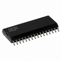
MFRC53101T/0FE,112 NXP Semiconductors, MFRC53101T/0FE,112 Datasheet - Page 16

MFRC53101T/0FE,112
Manufacturer Part Number
MFRC53101T/0FE,112
Description
IC MIFARE HS READER 32-SOIC
Manufacturer
NXP Semiconductors
Series
MIFARE®r
Specifications of MFRC53101T/0FE,112
Rf Type
Read Only
Frequency
13.56MHz
Features
ISO14443-A, ISO14443-B, ISO15693
Package / Case
32-SOIC (0.300", 7.50mm Width)
Product
RFID Readers
Operating Temperature Range
- 25 C to + 85 C
Lead Free Status / RoHS Status
Lead free / RoHS Compliant
Lead Free Status / RoHS Status
Lead free / RoHS Compliant, Lead free / RoHS Compliant
Other names
568-2224-5
935269691112
MFRC531
MFRC53101TD
935269691112
MFRC531
MFRC53101TD
Available stocks
Company
Part Number
Manufacturer
Quantity
Price
Part Number:
MFRC53101T/0FE,112
Manufacturer:
NXP/恩智浦
Quantity:
20 000
NXP Semiconductors
MFRC531_34
Product data sheet
PUBLIC
Fig 7.
Master key byte
Master key bits
EEPROM byte
Example
address
Key storage format
9.2.2.3 Register initialization file (read/write)
9.2.3.1 Key format
9.2.3 Crypto1 keys (write only)
k7 k6 k5 k4 k7 k6 k5 k4
5Ah
The EEPROM memory content from block address 3 to 7 can initialize register sub
addresses 10h to 2Fh when the LoadConfig command is executed (see
page
argument for the initialization procedure.
The byte assignment is shown in
Table 16.
The register initialization file is large enough to hold values for two initialization sets and
up to one block (16-byte) of user data.
Remark: The register initialization file can be read/written by users and these bytes can
be used to store other user data.
After each power-up, the default configuration enables the MIFARE and ISO/IEC 14443 A
protocol.
MIFARE security requires specific cryptographic keys to encrypt data stream
communication on the contactless interface. These keys are called Crypto1 keys.
Keys stored in the EEPROM are written in a specific format. Each key byte must be split
into lower four bits k0 to k3 (lower nibble) and the higher four bits k4 to k7 (higher nibble).
Each nibble is stored twice in one byte and one of the two nibbles is bit-wise inverted. This
format is a precondition for successful execution of the LoadKeyE2 (see
page
Using this format, 12 bytes of EEPROM memory are needed to store a 6-byte key. This is
shown in
Example: The value for the key must be written to the EEPROM.
EEPROM byte address
EEPROM starting byte address
EEPROM + 1 starting byte address
...
EEPROM + 31 starting byte address
n
•
•
If the key was: A0h A1h A2h A3h A4h A5h then:
5Ah F0h 5Ah E1h 5Ah D2h 5Ah C3h 5Ah B4h 5Ah A5h would be written.
86). This command requires the EEPROM starting byte address as a two byte
88) and LoadKey commands (see
0 (LSB)
k3 k2 k1 k0 k3 k2 k1 k0
Figure
Byte assignment for register initialization at startup
n + 1
F0h
7.
Rev. 3.4 — 26 January 2010
k7 k6 k5 k4 k7 k6 k5 k4
n + 2
5Ah
056634
Table
1
k3 k2 k1 k0 k3 k2 k1 k0
16.
Section 11.6.2 on page
n + 3
E1h
Register address
10h
11h
…
2Fh
k7 k6 k5 k4 k7 k6 k5 k4
n + 10
5Ah
ISO/IEC 14443 reader IC
88).
5 (MSB)
MFRC531
k3 k2 k1 k0 k3 k2 k1 k0
© NXP B.V. 2010. All rights reserved.
Section 11.4.1 on
Section 11.6.1 on
Remark
skipped
copied
…
copied
n + 11
A5h
001aak640
16 of 116


