AGLP-EVAL-KIT Actel, AGLP-EVAL-KIT Datasheet - Page 34
AGLP-EVAL-KIT
Manufacturer Part Number
AGLP-EVAL-KIT
Description
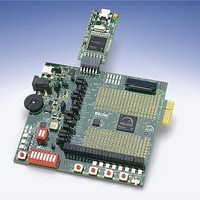
MCU, MPU & DSP Development Tools IGLOO PLUS Starter Kit
Manufacturer
Actel
Datasheet
1.AGLP-EVAL-KIT.pdf
(62 pages)
Specifications of AGLP-EVAL-KIT
Processor To Be Evaluated
CSG289
Interface Type
USB, JTAG
Operating Supply Voltage
1.2 V to 1.5 V
Lead Free Status / RoHS Status
Lead free / RoHS Compliant


Operation of Board Components
Flash*Freeze Switch
34
An F*F switch is provided on the board for designs that utilize the Flash*Freeze technology. Setting the F*F switch to
FF_ON will enable the Flash*Freeze mode of the IGLOO PLUS device. Since the Schmitt Trigger chip (U12) is NOT
populated on-board for the F*F switch, the Schmitt Trigger feature should be enabled in the FPGA design for the
Flash*Freeze input to enhance noise immunity
IGLOO PLUS FPGA family. If the IGLOO PLUS FPGA is swapped out with a device that does not have the
advanced Schmitt Trigger I/O feature, the Schmitt Trigger chip (U12) should be populated
Some features on this board are included to demonstrate the Flash*Freeze variants of the IGLOO PLUS FPGA. I/Os
can be individually configured to either hold their previous state or be tristated during Flash*Freeze mode. Alternatively,
they can be set to a certain state (high or low) using weak pull-up or pull-down I/O attribute configurations. These
Flash*Freeze variants can be demonstrated by configuring the I/Os in Designer and using switches as inputs to control
the FET LEDs. Refer to the demo design, which provides additional details on demonstrating these Flash*Freeze
variants
Buffer Type
Output
Bidirectional /
Notes:
1. Internal core logic driven by this input buffer will be set to the value this I/O had when entering Flash*Freeze mode.
2. Internal core logic driven by this input buffer will be tied High as long as the device is in Flash*Freeze mode.
3. For bidirectional buffers: Internal core logic driven by the input portion of the bidirectional buffer will be set to the hold state.
Tristate Buffer
Table 4-2 · IGLOO PLUS Flash*Freeze Mode (type 1 and type 2)—I/O Pad State (continued)
(“IGLOO PLUS Board Demo” on page
Mfr P/N :AYZ0102AGRL
Mfr: ITT INDUSTRIES
2
AYZ0102AGRL
AYZ0102AGRL
SW8
SW8
(input/tristate)
E = 1 (output)
3
1
E = 0
Figure 4-8 · Flash*Freeze Schematic, Schmitt Triggered
R61
R61
10K
10K
+ +
V3P3
Hold State
+ +
Disabled
Disabled
Disabled
Disabled
Disabled
Disabled
Enabled
Enabled
Enabled
Enabled
(Figure
51).
4-8). The Schmitt Trigger is an advanced I/O feature of the
Weak Pull-Up/-Down
1
2
3
U12
U12
Mfg P/N = SN74AUP1G17DCKR
Mfg P/N = SN74AUP1G17DCKR
Manufacturer = TI
Manufacturer = TI
NC
A
GND
"Don't care"
"Don't care"
I/O Pad
DNP
DNP
Disabled
Disabled
Disabled
Disabled
Enabled
Enabled
Enabled
Enabled
R52
R52
0
0
VCC
Y
IGLOO PLUS Starter Kit User’s Guide
5
4
Weak pull-up/pull-down
Weak pull-up/pull-down
Weak pull-up/pull-down
Weak pull-up/pull-down
Weak pull to hold state
V3P3
Weak pull to hold state
.
Flash*Freeze Mode
I/O Pad State in
Tristate
Tristate
Tristate
Tristate
IGLOO_FF [4]
1
2
3
1
2
Related parts for AGLP-EVAL-KIT
Image
Part Number
Description
Manufacturer
Datasheet
Request
R

Part Number:
Description:
MCU, MPU & DSP Development Tools Silicon Sculptor Programming Mod
Manufacturer:
Actel
Part Number:
Description:
MCU, MPU & DSP Development Tools InSystem Programming ProASICPLUS Devices
Manufacturer:
Actel
Part Number:
Description:
Programming Socket Adapters & Emulators PQ160 Module
Manufacturer:
Actel
Part Number:
Description:
Programming Socket Adapters & Emulators Axcelerator Adap Module Kit
Manufacturer:
Actel
Part Number:
Description:
Programming Socket Adapters & Emulators Evaluation
Manufacturer:
Actel
Part Number:
Description:
Programming Socket Adapters & Emulators AFDX Solutions
Manufacturer:
Actel
Part Number:
Description:
Programming Socket Adapters & Emulators SILICON SCULPTOR ADAPTER MODULE
Manufacturer:
Actel
Datasheet:
Part Number:
Description:
Programming Socket Adapters & Emulators Axcelerator Adap Module Kit
Manufacturer:
Actel
Part Number:
Description:
Programming Socket Adapters & Emulators Evaluation
Manufacturer:
Actel
Part Number:
Description:
Programming Socket Adapters & Emulators Silicon Sculptor Software
Manufacturer:
Actel
Part Number:
Description:
Programming Socket Adapters & Emulators InSystem Programming ProASICPLUS Devices
Manufacturer:
Actel
Part Number:
Description:
Programming Socket Adapters & Emulators Evaluation
Manufacturer:
Actel
Part Number:
Description:
Programming Socket Adapters & Emulators Axcelerator Adap Module Kit
Manufacturer:
Actel
Part Number:
Description:
Programming Socket Adapters & Emulators Axcelerator Adap Module Kit
Manufacturer:
Actel
Part Number:
Description:
Programming Socket Adapters & Emulators Axcelerator Adap Module Kit
Manufacturer:
Actel