AGLP-EVAL-KIT Actel, AGLP-EVAL-KIT Datasheet - Page 53
AGLP-EVAL-KIT
Manufacturer Part Number
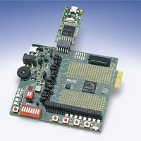
AGLP-EVAL-KIT
Description
MCU, MPU & DSP Development Tools IGLOO PLUS Starter Kit
Manufacturer
Actel
Datasheet
1.AGLP-EVAL-KIT.pdf
(62 pages)
Specifications of AGLP-EVAL-KIT
Processor To Be Evaluated
CSG289
Interface Type
USB, JTAG
Operating Supply Voltage
1.2 V to 1.5 V
Lead Free Status / RoHS Status
Lead free / RoHS Compliant


IGLOO PLUS Starter Kit User’s Guide
When HOLD is disabled at the output buffer, the output will depend on the resister pull-up or pull-down direction in
Flash*Freeze mode. If HOLD is enabled at the output buffer, then the output will depend on the state right before
entering Flash*Freeze mode.
1.
2.
3.
4.
5.
FET LED
FET LED D13
FET LED D14
FET LED D15
Similar to Demo 1, before starting Demo 4, check the jumper settings and set all switches to the OFF or CLOSED
position. Ensure the F*F switch is in the OFF position.
Power-on the IGLOO PLUS Starter Kit board using the power supply or USB cable included in the starter kit.
Press and release the System Reset button (SW7) to reset the IGLOO PLUS FPGA.
• Observe that LED D1 is ON during Reset.
Example A: Set both FET Switches [2:1] to the CLOSE position.
• Based on the logic in this demo design, both P-Type FET LEDs D13 and D14 should be ON and N-Type FET
• Enable Flash*Freeze mode by setting the F*F Switch to ON.
• Disable Flash*Freeze mode by setting the F*F Switch to OFF.
Example B: Set both FET Switches [2:1] to the OPEN position
• Based on the logic in this demo design, both P-type FET LEDs D13 and D14 should be OFF and N-type FET
• Enable Flash*Freeze mode by setting the F*F Switch to ON.
• Disable Flash*Freeze mode by setting the F*F to OFF.
LED D15 should be OFF. Refer to the board schematic for reference on the FET LED connections.
After entering Flash*Freeze mode, observe that P-Type FET LED D13 stays ON because the HOLD state for
this output configuration was enabled.
Also observe that P-Type FET LED D14 is ON due to the pull-down resister configuration.
N-Type FET LED D15 turns ON due to the pull-up resister configuration.
Toggle the FET Switches back and forth.
Return the FET Switches [2:1] back to the CLOSE position
After exiting the Flash*Freeze mode, observe that N-Type FET LED D15 turns OFF.
LED D15 should be ON.
After entering Flash*Freeze mode, observe that P-Type FET LED D13 remains OFF because the HOLD state
for this output configuration was enabled.
Also observe that P-Type FET LED D14 turns ON due to the pull-down resister configuration.
N-Type FET LED D15 is ON due to the pull-up resister configuration.
After exiting the Flash*Freeze mode, observe that P-Type FET LED D14 turns OFF.
Observe that the LEDs are unaffected, because the device is in Flash*Freeze mode. The inputs are not able
to pass data into the device.
Table 6-3 · FET Output Configuration in Demo Design
I/O Hold
Disabled
Disabled
Enabled
Getting Started with the IGLOO PLUS Starter Kit Demo Design
Internal Weak
Resister Pull
Down
Down
Up
Description
N-Type
P-Type
P-Type
53
Related parts for AGLP-EVAL-KIT
Image
Part Number
Description
Manufacturer
Datasheet
Request
R

Part Number:
Description:
MCU, MPU & DSP Development Tools Silicon Sculptor Programming Mod
Manufacturer:
Actel
Part Number:
Description:
MCU, MPU & DSP Development Tools InSystem Programming ProASICPLUS Devices
Manufacturer:
Actel
Part Number:
Description:
Programming Socket Adapters & Emulators PQ160 Module
Manufacturer:
Actel
Part Number:
Description:
Programming Socket Adapters & Emulators Axcelerator Adap Module Kit
Manufacturer:
Actel
Part Number:
Description:
Programming Socket Adapters & Emulators Evaluation
Manufacturer:
Actel
Part Number:
Description:
Programming Socket Adapters & Emulators AFDX Solutions
Manufacturer:
Actel
Part Number:
Description:
Programming Socket Adapters & Emulators SILICON SCULPTOR ADAPTER MODULE
Manufacturer:
Actel
Datasheet:
Part Number:
Description:
Programming Socket Adapters & Emulators Axcelerator Adap Module Kit
Manufacturer:
Actel
Part Number:
Description:
Programming Socket Adapters & Emulators Evaluation
Manufacturer:
Actel
Part Number:
Description:
Programming Socket Adapters & Emulators Silicon Sculptor Software
Manufacturer:
Actel
Part Number:
Description:
Programming Socket Adapters & Emulators InSystem Programming ProASICPLUS Devices
Manufacturer:
Actel
Part Number:
Description:
Programming Socket Adapters & Emulators Evaluation
Manufacturer:
Actel
Part Number:
Description:
Programming Socket Adapters & Emulators Axcelerator Adap Module Kit
Manufacturer:
Actel
Part Number:
Description:
Programming Socket Adapters & Emulators Axcelerator Adap Module Kit
Manufacturer:
Actel
Part Number:
Description:
Programming Socket Adapters & Emulators Axcelerator Adap Module Kit
Manufacturer:
Actel