AGLP-EVAL-KIT Actel, AGLP-EVAL-KIT Datasheet - Page 54
AGLP-EVAL-KIT
Manufacturer Part Number
AGLP-EVAL-KIT
Description
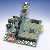
MCU, MPU & DSP Development Tools IGLOO PLUS Starter Kit
Manufacturer
Actel
Datasheet
1.AGLP-EVAL-KIT.pdf
(62 pages)
Specifications of AGLP-EVAL-KIT
Processor To Be Evaluated
CSG289
Interface Type
USB, JTAG
Operating Supply Voltage
1.2 V to 1.5 V
Lead Free Status / RoHS Status
Lead free / RoHS Compliant


IGLOO PLUS Board Demo
54
The FET Truth Table
configured for this demo design. For the output FET LEDs, NORMAL represents the LED state before entering and
after exiting Flash*Freeze mode, while F*F Mode represents the LED state during Flash*Freeze mode.
Input
FET
Switch 1
CLOSE (0)
CLOSE (0)
OPEN (1)
OPEN (1)
CLOSE (0)
CLOSE (0)
OPEN (1)
OPEN (1)
Switch 2
FET
(Table
6-4) shows the Flash*Freeze variants based on the FET I/O HOLD and resister pull
NORMAL
P-Type FET LED D13
OFF (1)
OFF (1)
(active low): HOLD
ON (0)
ON (0)
Table 6-4 · FET Truth Table
F*F Mode
OFF (1)
OFF (1)
ON (0)
ON (0)
P-Type FET LED D14
(active low): Pull-down
OFF (1)
OFF (1)
Normal
ON (0)
ON (0)
Output
F*F Mode
IGLOO PLUS Starter Kit User’s Guide
ON (0)
ON (0)
ON (0)
ON (0)
N-Type FET LED D15
(active high): Pull-up
OFF (0)
OFF (0)
Normal
ON (1)
ON (1)
F*F Mode
ON (1)
ON (1)
ON (1)
ON (1)
Related parts for AGLP-EVAL-KIT
Image
Part Number
Description
Manufacturer
Datasheet
Request
R

Part Number:
Description:
MCU, MPU & DSP Development Tools Silicon Sculptor Programming Mod
Manufacturer:
Actel
Part Number:
Description:
MCU, MPU & DSP Development Tools InSystem Programming ProASICPLUS Devices
Manufacturer:
Actel
Part Number:
Description:
Programming Socket Adapters & Emulators PQ160 Module
Manufacturer:
Actel
Part Number:
Description:
Programming Socket Adapters & Emulators Axcelerator Adap Module Kit
Manufacturer:
Actel
Part Number:
Description:
Programming Socket Adapters & Emulators Evaluation
Manufacturer:
Actel
Part Number:
Description:
Programming Socket Adapters & Emulators AFDX Solutions
Manufacturer:
Actel
Part Number:
Description:
Programming Socket Adapters & Emulators SILICON SCULPTOR ADAPTER MODULE
Manufacturer:
Actel
Datasheet:
Part Number:
Description:
Programming Socket Adapters & Emulators Axcelerator Adap Module Kit
Manufacturer:
Actel
Part Number:
Description:
Programming Socket Adapters & Emulators Evaluation
Manufacturer:
Actel
Part Number:
Description:
Programming Socket Adapters & Emulators Silicon Sculptor Software
Manufacturer:
Actel
Part Number:
Description:
Programming Socket Adapters & Emulators InSystem Programming ProASICPLUS Devices
Manufacturer:
Actel
Part Number:
Description:
Programming Socket Adapters & Emulators Evaluation
Manufacturer:
Actel
Part Number:
Description:
Programming Socket Adapters & Emulators Axcelerator Adap Module Kit
Manufacturer:
Actel
Part Number:
Description:
Programming Socket Adapters & Emulators Axcelerator Adap Module Kit
Manufacturer:
Actel
Part Number:
Description:
Programming Socket Adapters & Emulators Axcelerator Adap Module Kit
Manufacturer:
Actel