AGLP-EVAL-KIT Actel, AGLP-EVAL-KIT Datasheet - Page 7
AGLP-EVAL-KIT
Manufacturer Part Number
AGLP-EVAL-KIT
Description
MCU, MPU & DSP Development Tools IGLOO PLUS Starter Kit
Manufacturer
Actel
Datasheet
1.AGLP-EVAL-KIT.pdf
(62 pages)
Specifications of AGLP-EVAL-KIT
Processor To Be Evaluated
CSG289
Interface Type
USB, JTAG
Operating Supply Voltage
1.2 V to 1.5 V
Lead Free Status / RoHS Status
Lead free / RoHS Compliant


Board Components and Settings
Board Description
IGLOO PLUS Starter Kit User’s Guide
This chapter describes the components and settings for the IGLOO PLUS Starter Kit Board.
The IGLOO PLUS Starter Kit board is intended to provide a low-cost system platform for evaluating IGLOO PLUS
(AGLP) technology, such as low power, I/O state preservation during Flash*Freeze mode, and Schmitt Triggered I/Os.
Other advanced features include the ability to use the FPGA I/Os of the Expansion Header as hot-swappable and the
Schmitt Triggered FPGA inputs for improved noise immunity.
This evaluation board enables you to measure power consumption (dynamic, static, and Flash*Freeze modes) with the
core operating between 1.2 V and 1.5 V. When using the board in conjunction with Actel’s power analysis tools, you will
have a clear picture of application power consumption at each stage in your design. In addition, the Libero® Integrated
Design Environment (IDE) tool suite now includes power-driven layout (PDL), which can reduce the power
consumption of designs up to 30 percent.
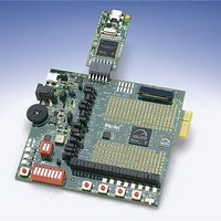
The evaluation board has a small form factor, measuring 3.7 inches by 4 inches, and supports an AGLP125 IGLOO
PLUS device in the 14 mm × 14 mm CSG289 package. All components used on the board, such as LEDs, reset (μA
range), and oscillator, are low-power components. Also included on the evaluation board is a USB-to-UART interface
to allow HyperTerminal on a PC to communicate with the IGLOO PLUS device on the board.
The top of the board has a programming stick header which allows the low-cost programming stick (LCPS) to be
attached to the board for programming the IGLOO PLUS AGLP125-CSG289 device
I/Os have been wired to test pin pads on the board for debug and expandability.
Note:
The clock oscillator for the IGLOO PLUS Starter Kit Board is behind the board.
Figure 1-1 · IGLOO PLUS Starter Kit Board
(Figure 1-1 on page
7). FPGA
1
7
Related parts for AGLP-EVAL-KIT
Image
Part Number
Description
Manufacturer
Datasheet
Request
R

Part Number:
Description:
MCU, MPU & DSP Development Tools Silicon Sculptor Programming Mod
Manufacturer:
Actel
Part Number:
Description:
MCU, MPU & DSP Development Tools InSystem Programming ProASICPLUS Devices
Manufacturer:
Actel
Part Number:
Description:
Programming Socket Adapters & Emulators PQ160 Module
Manufacturer:
Actel
Part Number:
Description:
Programming Socket Adapters & Emulators Axcelerator Adap Module Kit
Manufacturer:
Actel
Part Number:
Description:
Programming Socket Adapters & Emulators Evaluation
Manufacturer:
Actel
Part Number:
Description:
Programming Socket Adapters & Emulators AFDX Solutions
Manufacturer:
Actel
Part Number:
Description:
Programming Socket Adapters & Emulators SILICON SCULPTOR ADAPTER MODULE
Manufacturer:
Actel
Datasheet:
Part Number:
Description:
Programming Socket Adapters & Emulators Axcelerator Adap Module Kit
Manufacturer:
Actel
Part Number:
Description:
Programming Socket Adapters & Emulators Evaluation
Manufacturer:
Actel
Part Number:
Description:
Programming Socket Adapters & Emulators Silicon Sculptor Software
Manufacturer:
Actel
Part Number:
Description:
Programming Socket Adapters & Emulators InSystem Programming ProASICPLUS Devices
Manufacturer:
Actel
Part Number:
Description:
Programming Socket Adapters & Emulators Evaluation
Manufacturer:
Actel
Part Number:
Description:
Programming Socket Adapters & Emulators Axcelerator Adap Module Kit
Manufacturer:
Actel
Part Number:
Description:
Programming Socket Adapters & Emulators Axcelerator Adap Module Kit
Manufacturer:
Actel
Part Number:
Description:
Programming Socket Adapters & Emulators Axcelerator Adap Module Kit
Manufacturer:
Actel