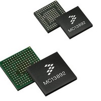
MC13892AJVL Freescale Semiconductor, MC13892AJVL Datasheet - Page 57

MC13892AJVL
Manufacturer Part Number
MC13892AJVL
Description
IC PMU I.MX51/37/35/27 186MAPBGA
Manufacturer
Freescale Semiconductor
Datasheets
1.MC13892AJVLR2.pdf
(156 pages)
2.MC13892AJVLR2.pdf
(2 pages)
3.MC13892AJVLR2.pdf
(16 pages)
4.MC13892AJVLR2.pdf
(5 pages)
Specifications of MC13892AJVL
Applications
Battery Management, Display (LED Drivers), Handheld/Mobile Devices, Power Supply
Operating Temperature
-40°C ~ 85°C
Mounting Type
Surface Mount
Package / Case
186-LFBGA
Mounting Style
SMD/SMT
Duty Cycle (max)
55 %
Input Voltage
- 0.3 V to + 20 V
Maximum Operating Temperature
+ 85 C
Minimum Operating Temperature
- 30 C
Output Current
30 mA
Output Voltage
3.3 V
Topology
Boost
Operating Temperature (max)
85C
Operating Temperature (min)
-40C
Mounting
Surface Mount
Package Type
BGA
Case Length
12mm
Screening Level
Industrial
Lead Free Status / RoHS Status
Lead free / RoHS Compliant
Current - Supply
-
Voltage - Supply
-
Lead Free Status / Rohs Status
Lead free / RoHS Compliant
Available stocks
Company
Part Number
Manufacturer
Quantity
Price
Company:
Part Number:
MC13892AJVL
Manufacturer:
Freescale Semiconductor
Quantity:
10 000
Part Number:
MC13892AJVL
Manufacturer:
FREESCALE
Quantity:
20 000
Company:
Part Number:
MC13892AJVLR2
Manufacturer:
Freescale Semiconductor
Quantity:
10 000
POWER CONTROL MODES DESCRIPTION
complement
interrupt line INT is kept low in all states except for Watchdog and On.
Off
all other supplies are inactive. To exit the Off mode, a valid turn on event is required. No specific timer is running in this mode.
powered from LICELL. The only active circuitry is the RTC module, with BP greater than UVDET detection, and the SRTC support
circuitry, if so configured.
Cold Start
are powered up sequentially to limit the inrush current. See the Power Up section for sequencing and default level details. The
reset signals RESETB and RESETBMCU are kept low. The Reset timer starts running when entering a Cold Start. When expired,
the Cold Start state is exited for the Watchdog state, and both RESETB and RESETBMCU become high (open drain output with
external pull ups). The input control pins WDI, and STANDBYx are ignored.
Watchdog
when entering the Watchdog state. When expired, the system transitions to the On state, where WDI will be checked and
monitored. The input control pins WDI and STANDBYx are ignored while in the Watchdog state.
On
in this mode. The WDI IO supply voltage is referenced to SPIVCC (Normally connected to SW4). SPIVCC must therefore remain
enabled to allow for proper WDI detection. If WDI goes low, the system will transition to the Off state or Cold Start (depending on
the configuration. Refer to the section on Silent System Restart with WDI Event for details).
User Off Wait
by a processor request for User Off by setting the USEROFFSPI bit high. This is normally initiated by the end user via the power
key. Upon receiving the corresponding interrupt, the system will determine if the product has been configured for User Off or
Memory Hold states (both of which first require passing through User Off Wait) or just transition to Off.
tasks. When expired, the Wait mode is exited for User Off mode or Memory Hold mode, depending on warm starts being enabled
or not via the WARMEN bit. The USEROFFSPI bit is being reset at this point by RESETB going low.
Memory Hold and User Off (Low Power Off states)
response to an intentional turn off by the end user. The only exit then will be a turn on event. To an end user, the Memory Hold
and User Off states look like the product has been shut down completely. However, a faster startup is facilitated by maintaining
external memory in self-refresh mode (Memory Hold and User Off mode) as well as powering portions of the processor core for
state retention (User Off only). The switcher mode control bits allow selective powering of the buck switchers for optimizing the
supply behavior in the Low Power Off modes. Linear regulators and most functional blocks are disabled (the RTC module, and
Turn On event detection are maintained).
Memory Hold
kept active. To ensure that SW1, SW2, and SW3 shut off in Memory Hold, appropriate mode settings should be used such as
SW1MHMODE = SW2MHMODE = SW3MHMODE = 0 (refer to the mode control description later in this chapter). Since SW4
should be powered in PFM mode, SW4MHMODE could be set to 1.
Analog Integrated Circuit Device Data
Freescale Semiconductor
Following are text descriptions of the power states of the system, which give additional details of the state machine, and
If the supply at BP is above the UVDET threshold, only the IC core circuitry at VCOREDIG and the RTC module are powered,
If the supply at BP is below the UVDET threshold no turn on events are accepted. If a valid coin cell is present, the core gets
Entered upon a Turn On event from Off, Warm Boot, successful PCUT, or Silent System Restart. The switchers and regulators
The system is fully powered and under SPI control. RESETB and RESETBMCU are high. The Watchdog timer starts running
The system is fully powered and under SPI control. RESETB and RESETBMCU are high. The WDI pin must be high to stay
The system is fully powered and under SPI control. The WDI pin no longer has control over the part. The Wait mode is entered
The Wait timer starts running when entering User Off Wait mode. This leaves the processor time to suspend or terminate its
As noted in the User Off Wait description, the system is directed into low power Off states based on a SPI command in
RESETB and RESETBMCU are low, and both CLK32K and CLK32KMCU are disabled. If DRM is set, the CLK32KMCU is
Figure
11. Note that the SPI control is only possible in the Watchdog, On, and User Off Wait states, and that the
FUNCTIONAL DEVICE OPERATION
OPERATING MODES
13892
57


