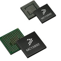
MC13892AJVL Freescale Semiconductor, MC13892AJVL Datasheet - Page 92

MC13892AJVL
Manufacturer Part Number
MC13892AJVL
Description
IC PMU I.MX51/37/35/27 186MAPBGA
Manufacturer
Freescale Semiconductor
Datasheets
1.MC13892AJVLR2.pdf
(156 pages)
2.MC13892AJVLR2.pdf
(2 pages)
3.MC13892AJVLR2.pdf
(16 pages)
4.MC13892AJVLR2.pdf
(5 pages)
Specifications of MC13892AJVL
Applications
Battery Management, Display (LED Drivers), Handheld/Mobile Devices, Power Supply
Operating Temperature
-40°C ~ 85°C
Mounting Type
Surface Mount
Package / Case
186-LFBGA
Mounting Style
SMD/SMT
Duty Cycle (max)
55 %
Input Voltage
- 0.3 V to + 20 V
Maximum Operating Temperature
+ 85 C
Minimum Operating Temperature
- 30 C
Output Current
30 mA
Output Voltage
3.3 V
Topology
Boost
Operating Temperature (max)
85C
Operating Temperature (min)
-40C
Mounting
Surface Mount
Package Type
BGA
Case Length
12mm
Screening Level
Industrial
Lead Free Status / RoHS Status
Lead free / RoHS Compliant
Current - Supply
-
Voltage - Supply
-
Lead Free Status / Rohs Status
Lead free / RoHS Compliant
Available stocks
Company
Part Number
Manufacturer
Quantity
Price
Company:
Part Number:
MC13892AJVL
Manufacturer:
Freescale Semiconductor
Quantity:
10 000
Part Number:
MC13892AJVL
Manufacturer:
FREESCALE
Quantity:
20 000
Company:
Part Number:
MC13892AJVLR2
Manufacturer:
Freescale Semiconductor
Quantity:
10 000
FUNCTIONAL DEVICE OPERATION
BATTERY INTERFACE AND CONTROL
POWER DISSIPATION
the external pass FETs M1 and M2 are not over dissipating when charging. By default, the charge system will protect against
this by a built-in power limitation circuit. This circuit will monitor the voltage drop between CHRGRAW and CHRGISNS, and the
current through the external sense resistor connected between CHRGISNS and BPSNS. When required,.a duty cycle is applied
to the M1 and M2 drivers and thus the charge current, in order to stay within the power budget. At the same time M3 is forced to
conduct to keep the application powered. In case of excessive supply conditions, the power limiter minimum duty cycle may not
be sufficiently small to maintain the actual power dissipation within budget. In that case, the charge path will be disabled and the
CHGFAULTI interrupt generated with the CHGFAULTS[1:0] bits set to 01.
setting the PLIMDIS bit. In this case, it is advised to use close software control to estimate the dissipated power in the external
pass FETs. The power limiter is automatically disabled in serial path factory mode and in reverse mode.
are intended for PLIM[1:0] and PLIMDIS, should be programmed early in the configuration sequence, to ensure proper supply
conditions adapted to the application. To avoid any false detection during power up, the power limiter output is blanked at the
start of the charge cycle. As a safety precaution though, the power dissipation is monitored and the desired duty cycle is
estimated. When this estimated duty cycle falls below the power limiter minimum duty cycle, the charger circuit will be disabled.
REVERSE SUPPLY MODE
current through the accessory supply path is monitored via the charge path sense resistor R2, and can be read out via the ADC.
The accessory supply path is disabled and an interrupt CHGSHORTI is generated when the slow or fast threshold is crossed.
The reverse path is disabled when a current reversal occurs and an interrupt CHREVI is generated.
92
Table 67. Charger Power Dissipation Limiter Characteristics
13892
Table 68. Accessory Supply Main Characteristics
Power Limiter Accuracy
Power Limiter Control Period
Power Limiter Blanking Period
Power Limiter Minimum Duty Cycle
Since the charge path operates in a linear fashion, the dissipation can be significant and care must be taken to ensure that
The power budget can be programmed by SPI through the PLIM[1:0] bits. The power dissipation limiter can be disabled by
Since a charger attachment can be a Turn-on event when a product is initially in the Off state, any non-default settings that
The battery voltage can be applied to an external accessory via the charge path, by setting the RVRSMODE bit high. The
Short-circuit Current Slow Threshold
Slow Threshold Debounce Time
Short-circuit Current Fast Threshold
Fast Threshold Debounce Time
Current Reversal Threshold
Parameter
Parameter
Table 66. Charger Power Dissipation Limiter Control
PLIM[1:0]
00 (default)
01
10
11
Up to 2x the power set by PLIM[1:0]
Upon charging enabling
Current from Accessory
Condition
Condition
Power Limit (mW)
1000
1200
600
800
Min
500
-
-
-
-
Min
-
-
-
-
Analog Integrated Circuit Device Data
CHGCURR
Typ
100
1.0
Typ
1500
-
-
500
10
-
Freescale Semiconductor
Max
Max
1840
15
-
-
-
-
-
-
-
Units
Units
mA
mA
mA
ms
μs
ms
ms
%
%


