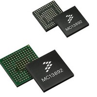
MC13892AJVL Freescale Semiconductor, MC13892AJVL Datasheet - Page 94

MC13892AJVL
Manufacturer Part Number
MC13892AJVL
Description
IC PMU I.MX51/37/35/27 186MAPBGA
Manufacturer
Freescale Semiconductor
Datasheets
1.MC13892AJVLR2.pdf
(156 pages)
2.MC13892AJVLR2.pdf
(2 pages)
3.MC13892AJVLR2.pdf
(16 pages)
4.MC13892AJVLR2.pdf
(5 pages)
Specifications of MC13892AJVL
Applications
Battery Management, Display (LED Drivers), Handheld/Mobile Devices, Power Supply
Operating Temperature
-40°C ~ 85°C
Mounting Type
Surface Mount
Package / Case
186-LFBGA
Mounting Style
SMD/SMT
Duty Cycle (max)
55 %
Input Voltage
- 0.3 V to + 20 V
Maximum Operating Temperature
+ 85 C
Minimum Operating Temperature
- 30 C
Output Current
30 mA
Output Voltage
3.3 V
Topology
Boost
Operating Temperature (max)
85C
Operating Temperature (min)
-40C
Mounting
Surface Mount
Package Type
BGA
Case Length
12mm
Screening Level
Industrial
Lead Free Status / RoHS Status
Lead free / RoHS Compliant
Current - Supply
-
Voltage - Supply
-
Lead Free Status / Rohs Status
Lead free / RoHS Compliant
Available stocks
Company
Part Number
Manufacturer
Quantity
Price
Company:
Part Number:
MC13892AJVL
Manufacturer:
Freescale Semiconductor
Quantity:
10 000
Part Number:
MC13892AJVL
Manufacturer:
FREESCALE
Quantity:
20 000
Company:
Part Number:
MC13892AJVLR2
Manufacturer:
Freescale Semiconductor
Quantity:
10 000
FUNCTIONAL DEVICE OPERATION
BATTERY INTERFACE AND CONTROL
interrupts can be used as a simple way to implement a 3-bar battery meter.
BATTERY THERMISTOR CHECK CIRCUITRY
temperature T (in Kelvin) and the thermistor value (RT) is well characterized and can be described as RT = R0*e^(B*(1/T-1/T0),
with T0 being room temperature, R0 the thermistor value at T0 and B being the so called B-factor which indicates the slope of
the thermistor over temperature. In order to read out the thermistor value, it is biased from GPO1 through a pull-up resistor R
See also the ADC chapter. The battery thermistor check circuit compares the fraction of GPO1 at ADIN5 with two preset
thresholds, which correspond to 0 and 45 °C, see
see next section for details.
CHARGE LED INDICATOR
at the CHRGLED pin for an LED connected to CHRGRAW.
the application is powered on. At the end of charge, the LED is automatically disabled. Through the CHRGLEDEN bit, the LED
can be forced on. In software controlled charging, the LED is under full control of this CHRGLEDEN bit.
Table 74. Charge LED Drivers Main Characteristics
94
Table 73. Battery Thermistor Check Main Characteristics
13892
Table 72. Charger Detectors main characteristics
Notes
69.
Temperature Threshold
Trickle LED current
Tlow
Thigh
Charger Valid
CHGCURR Threshold
Debounce Period
Crossing the thresholds BATTCYCL and CHGCURR will generate the interrupts CCCVI and CHGCURRI respectively. These
A battery pack may be equipped with a thermistor, which value decreases over temperature (NTC). The relationship between
Since normal LED control via the SPI bus is not always possible in the charging mode, an 8.0 mA max current sink is provided
The LED will be activated when standalone charging is started, and will remain under control of the state machine also when
Above conditions represent respectively a USB and a collapsed charger case
Parameter
Parameter
24/32 * GPO1
10/32 * GPO1
Voltage at ADIN5
CHRGRAW
CHRGISNS-BPSNS, current from charger
BATTMIN, BATTON rising edge (normal
BATTMIN, BATTON rising edge (slow)
BATTMIN falling edge (slow)
BATTMIN falling edge (fast)
BATTCYCL dual edge
CHGCURR
Charger Detect dual edge
Table 75. Charge LED Driver Control
CHRGLED = 2.5 V
CHRGLED = 0.7 V
CHRGLEDEN
Table
0 (default)
Condition
Corresponding Resistor Values
1
73. Charging is generally allowed when the thermistor is within the range,
Rpu
10 k
10 k
Condition
30 k
45 k
RT
CHRGLED
Auto
On
Min
10
-
-
-
-
-
-
-
-
Min
5.0
-
B=3200
Corresponding Temperature (in °C) *
-3.0
+49
Analog Integrated Circuit Device Data
Typ
100
100
3.8
1.0
1.0
1.0
1.0
32
-
Typ
-
-
B=3500
Freescale Semiconductor
+46
Max
0
50
-
-
-
-
-
-
-
-
Max
8.0
-
B=3900
Units
+2.0
+44
mA
Units
ms
ms
ms
ms
V
s
s
s
mA
mA
PU
.


