MC13892JVL Freescale Semiconductor, MC13892JVL Datasheet
MC13892JVL
Specifications of MC13892JVL
Available stocks


Related parts for MC13892JVL


MC13892JVL Summary of contents
Page 1
... MC13892VK includes 139 balls including 4 sets of triple corner balls total 131 assigned signal pins, where the MC13892VL includes 186 balls, all of which are assigned signal pins. © Freescale Semiconductor, Inc., 2010. All rights reserved. Rev. 1.0, 3/2010 Contents 1 Purpose ...
Page 2
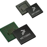
... PACKAGING 13892 2 Figure 1. MC13892JVK Package Analog Integrated Circuit Device Data Freescale Semiconductor ...
Page 3
... Analog Integrated Circuit Device Data Freescale Semiconductor Figure 2. MC13892JVL Package PACKAGING 13892 3 ...
Page 4
... PACKAGING 3.1 Recommended Footprints The MC13892JVK footprint consists of 10 mil pads with a 19.68 mil pitch, and the MC13892JVL footprint has 16 mil pads with a 31.496mil pitch. These are recommended as shown in Figure 3. Recommended Footprint for the MC13892JVK (Top View) Figure 4. Recommended Footprint for the MC13892JVL (Top View) ...
Page 5
... SPIVC C PW GTDRV1 L GNDSW EN3 GEN2 VSRTC GND RTC N VG EN3 VGEN 3 VIN GEN3D RV VGE N2DR V Analog Integrated Circuit Device Data Freescale Semiconductor GN DBL ORE LED B LED KP LEDR GND CORE VCOREDIG LEDMD DV S1 REFC ORE CHR GSE1B LIC ELL B ATTFE T UID ...
Page 6
... GNDSUB GNDSUB VCAM VINAUDIO VDIG GNDSUB STANDBY VINCAMDRV CFP CFM VGEN1DRV XTAL1 VAUDIO PWGTDRV2 VIOHI VINIOHI GNDRTC GNDSUB GNDSUB GNDSUB GNDSUB Figure 6. MC13892JVL Pinout Layer Stack-up Layer 1 (Top) Signal Fanout/Ground Power Signal/Ground CHRGRAW CHRGCTRL2 CHRGISNS BP GNDCHRG BATTISNSCC BATTISNS BATTFET BPSNS GPO3 ...
Page 7
... The rest of the layers can have 1.0 oz copper thickness for better current handling. Care must be taken on these layers that the separation is more than 5.0 mils between traces, vias, pads, and planes. Reference Analog Integrated Circuit Device Data Freescale Semiconductor NOTE Figure 7. ...
Page 8
... The problem with through vias is that, since they go through the entire 13892 8 Figure 7. Pin Escape for the MC13892VK and Figure 5) to route critical Switching Power Supplies Traces. Analog Integrated Circuit Device Data Freescale Semiconductor ...
Page 9
... Care must be taken with these signals not to contaminate analog signals, as they are high frequency signals. Another good practice is to trace them perpendicularly on different layers so there is a minimum area of proximity between signals. Analog Integrated Circuit Device Data Freescale Semiconductor SPI/I2C COMMUNICATION AND REAL TIME CLOCK SIGNALS DON’T! DO ...
Page 10
... VIN If a schottcky diode is anticipated LX FB Figure 9. Current flow on a buck converter. VIN capable of handling 1.0 ampere. Therefore, a trace that will carry ON phase OFF phase High di/dt trace High di/dt traces if schottky diode added Analog Integrated Circuit Device Data Freescale Semiconductor ...
Page 11
... CIN will continue to prevent a drop on the input supply during large load transients. Note: The recommended value for this capacitor on this application is 4.7 μF. Analog Integrated Circuit Device Data Freescale Semiconductor silicon Rboard1 Vc ...
Page 12
... Figure 14. Current Flow on a Boost Converter. 13892 12 VIN High current (up to 1.3A) and High di/dt trace (up to 500e9 A/s) High current (up to 1.3A) Low, DCR LX Very noisy signal Cout SWGND FB FB LOAD ON phase OFF phase Analog Integrated Circuit Device Data Freescale Semiconductor ...
Page 13
... Any perturbation on this line must be minimized to ensure the stability of the switcher. Figure 17 shows the recommended configuration for the MC13892 power management IC, to stabilize the voltage on the switcher line. Analog Integrated Circuit Device Data Freescale Semiconductor High di/dt trace Low di/dt trace FB High di/dt trace ...
Page 14
... Charge path can handle up to 1600 mA, so following the rule listed previously, for 1.0 oz copper, the trace width must be at least 16 mils placement suggestion, the thermistor must be located as close to the battery as possible for a correct temperature reading. 13892 14 Figure 17. Recommended Configuration. Analog Integrated Circuit Device Data Freescale Semiconductor ...
Page 15
... References • MC13892 Data sheet Analog Integrated Circuit Device Data Freescale Semiconductor REFERENCES 13892 15 ...
Page 16
... Freescale Semiconductor was negligent regarding the design or manufacture of the part. Freescale™ and the Freescale logo are trademarks of Freescale Semiconductor, Inc ...