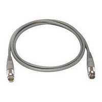
11730D AGILENT TECHNOLOGIES, 11730D Datasheet - Page 124

11730D
Manufacturer Part Number
11730D
Description
SENSOR CABLE, 50FT
Manufacturer
AGILENT TECHNOLOGIES
Datasheet
1.11730D.pdf
(234 pages)
Specifications of 11730D
Leaded Process Compatible
No
Peak Reflow Compatible (260 C)
No
Cable Length
50ft
Features
Reduces RFI Effect On Low Power Readings With Improved Shielding Design
Cable Assembly Type
Sensor
Cable Color
Gray
Rohs Compliant
No
For Use With
8480 & E-Series Power Sensors
Lead Free Status / RoHS Status
Contains lead / RoHS non-compliant
- Current page: 124 of 234
- Download datasheet (7Mb)
Isolation calculation characteristics
Isolation and insertion loss vary with frequency and depend on the
port selected as shown in the chart and tables below. The input
connector “C” is always defined as the connector at the end of
the switch opposite the DC drive cable. The output ports are
numbered sequentially from the input connector. For example, if
an Agilent 8768K is being used, use the Agilent 8768K table to
determine the isolation to each port. If port three (the third
connector from the input) is selected, the isolation to ports 1and 2
Agilent 8766K SP3T switch
Isolation (dB)
Agilent 8767K SP4T switch
120
100
80
60
40
20
Section
Common to Port 1
Common to Port 1
Common to Port 2
Common to Port 3
Section
Common to Port 1
Common to Port 1
Common to Port 1
Common to Port 1
Common to Port 2
Common to Port 2
Common to Port 3
Common to Port 4
0
2
4
1
Select
Select
Select
Select
Bypass
Bypass
Bypass
Bypass
1
Select
Select
Bypass
Bypass
6
Section status
Section status
8
2
Select
Select
Bypass
Bypass
Select
Select
Bypass
Bypass
2
Select
Bypass
Select
Bypass
10
Frequency (GHz)
3
Select
Bypass
Select
Bypass
Select
Bypass
Select
Bypass
12
14
1
—
—
A
A
16
1
—
—
—
—
A
A
A
A
will follow curve A. Isolation to port 4 will follow curve B and
isolation to port 5 will follow curve C. At 8 GHz, the worst case
isolation to ports 1 and 2 will be 30 dB; to port 4, 45 dB, and to
port 5, 65 dB. Note: in selecting ports 1 or 2, isolation to
disconnected ports can be varied by choosing the position of
each section to “bypass” or “select”. Depending on the user’s
application, port assignments can be critical for optimizing
performance at higher frequencies.
18
Isolation curve for Port ( )
Isolation curve for Port ( )
2
B
C
—
A
2
B
B
C
C
—
—
A
A
20
Low Profile Multiport Switch (continued)
www.agilent.com/find/mta
22
3
D
E
B
C
B
C
—
A
3
D
B
B
—
24
26.5
4
E
D
C
B
C
B
A
—
A
G
F
E
D
C
B
Switches
113
15
Related parts for 11730D
Image
Part Number
Description
Manufacturer
Datasheet
Request
R

Part Number:
Description:
Agilent Tachyon DX4+ (HPFC-5700) Dual-Channel 4-Gb Fibre Channel Controller With The Data Integrity Field (DIF) Feature
Manufacturer:
Agilent Technologies, Inc.

Part Number:
Description:
Manufacturer:
Agilent Technologies, Inc.
Datasheet:

Part Number:
Description:
Manufacturer:
Agilent Technologies, Inc.
Datasheet:

Part Number:
Description:
Manufacturer:
Agilent Technologies, Inc.
Datasheet:

Part Number:
Description:
Manufacturer:
Agilent Technologies, Inc.
Datasheet:

Part Number:
Description:
Manufacturer:
Agilent Technologies, Inc.
Datasheet:

Part Number:
Description:
Manufacturer:
Agilent Technologies, Inc.
Datasheet:

Part Number:
Description:
Manufacturer:
Agilent Technologies, Inc.
Datasheet:

Part Number:
Description:
Manufacturer:
Agilent Technologies, Inc.
Datasheet:

Part Number:
Description:
Manufacturer:
Agilent Technologies, Inc.
Datasheet:

Part Number:
Description:
Manufacturer:
Agilent Technologies, Inc.
Datasheet:

Part Number:
Description:
Manufacturer:
Agilent Technologies, Inc.
Datasheet:

Part Number:
Description:
1.0625 GBd Fibre Channel 10x10 mm QFP Transceiver Chip (Recommend HDMP-1636A for new designs)
Manufacturer:
Agilent Technologies, Inc.
Datasheet:

Part Number:
Description:
Manufacturer:
Agilent Technologies, Inc.
Datasheet:

Part Number:
Description:
1.0625-2.125 GBd Serdes Circuits: SSTL_2
Manufacturer:
Agilent Technologies, Inc.
Datasheet:


