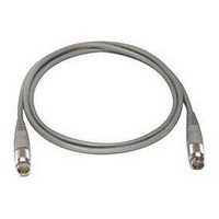
11730D AGILENT TECHNOLOGIES, 11730D Datasheet - Page 75

11730D
Manufacturer Part Number
11730D
Description
SENSOR CABLE, 50FT
Manufacturer
AGILENT TECHNOLOGIES
Datasheet
1.11730D.pdf
(234 pages)
Specifications of 11730D
Leaded Process Compatible
No
Peak Reflow Compatible (260 C)
No
Cable Length
50ft
Features
Reduces RFI Effect On Low Power Readings With Improved Shielding Design
Cable Assembly Type
Sensor
Cable Color
Gray
Rohs Compliant
No
For Use With
8480 & E-Series Power Sensors
Lead Free Status / RoHS Status
Contains lead / RoHS non-compliant
- Current page: 75 of 234
- Download datasheet (7Mb)
64
9
Directional Couplers and Bridges
Directional Couplers and Bridges
Applications
Directional couplers are general purpose tools used in RF and
microwave signal routing for isolating, separating or combining
signals. They find use in a variety of measurement applications:
• Power monitoring
• Source leveling
• Isolation of signal sources
• Swept transmission and reflection measurements
Key specifications
The key specifications for a directional coupler depend on its
application. Each of them should be carefully evaluated to ensure
that the coupler meets its intended use.
• Directivity
• SWR
• Coupling coefficient
• Transmission loss
• Input power
Directivity
Directivity is a measure of how well the coupler isolates two
opposite-travelling (forward and reverse) signals. In the case of
measuring reflection coefficient (return loss) of a device under test,
directivity is a crucial parameter in the uncertainty of the result.
Figure 1 shows how the reflection signal, E r , is degraded by the
undesired portion of the incident signal D 2 . And since the
undesired signal, D 2 , combines with the reflected signal as a
phasor, the error in the measured signal Em 2 can only be
compensated or corrected on a broadband basis using
vector analyzers.
Because the reverse-coupled signal is very small, it adds a
negligible amount of uncertainty when measuring large
reflections. But as the reflected signal becomes smaller, the
reverse-coupled signal becomes more significant.
For example, when the return loss in dB equals the value of
directivity, the measurement error can be between –6 to +8 dB.
The higher the directivity specified in dB, the higher the
measurement accuracy. The effect of the directivity error on the
forward-coupler output, Em
desired signal is usually a large value. When Agilent couplers are
used for power monitoring and leveling, directivity is less
important than coupling coefficient flatness.
Figure 1. Effect of directivity on reflection measurement.
E
K and K : Coupling coefficients (dB)
D and D : Directivities (dB)
E =
E =
E =
in
m
in
1
1
r
2
2
Input signal
Reflected signal from DUT
Measured signal (includes directivity error)
E K
in
K
1
1
D
1
D
Em1
1
1
, is less important because the
E K
D
r
2
2
D
2
K
Em2
2
Device
under
test
Related parts for 11730D
Image
Part Number
Description
Manufacturer
Datasheet
Request
R

Part Number:
Description:
Agilent Tachyon DX4+ (HPFC-5700) Dual-Channel 4-Gb Fibre Channel Controller With The Data Integrity Field (DIF) Feature
Manufacturer:
Agilent Technologies, Inc.

Part Number:
Description:
Manufacturer:
Agilent Technologies, Inc.
Datasheet:

Part Number:
Description:
Manufacturer:
Agilent Technologies, Inc.
Datasheet:

Part Number:
Description:
Manufacturer:
Agilent Technologies, Inc.
Datasheet:

Part Number:
Description:
Manufacturer:
Agilent Technologies, Inc.
Datasheet:

Part Number:
Description:
Manufacturer:
Agilent Technologies, Inc.
Datasheet:

Part Number:
Description:
Manufacturer:
Agilent Technologies, Inc.
Datasheet:

Part Number:
Description:
Manufacturer:
Agilent Technologies, Inc.
Datasheet:

Part Number:
Description:
Manufacturer:
Agilent Technologies, Inc.
Datasheet:

Part Number:
Description:
Manufacturer:
Agilent Technologies, Inc.
Datasheet:

Part Number:
Description:
Manufacturer:
Agilent Technologies, Inc.
Datasheet:

Part Number:
Description:
Manufacturer:
Agilent Technologies, Inc.
Datasheet:

Part Number:
Description:
1.0625 GBd Fibre Channel 10x10 mm QFP Transceiver Chip (Recommend HDMP-1636A for new designs)
Manufacturer:
Agilent Technologies, Inc.
Datasheet:

Part Number:
Description:
Manufacturer:
Agilent Technologies, Inc.
Datasheet:

Part Number:
Description:
1.0625-2.125 GBd Serdes Circuits: SSTL_2
Manufacturer:
Agilent Technologies, Inc.
Datasheet:


