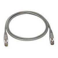
11730D AGILENT TECHNOLOGIES, 11730D Datasheet - Page 76

11730D
Manufacturer Part Number
11730D
Description
SENSOR CABLE, 50FT
Manufacturer
AGILENT TECHNOLOGIES
Datasheet
1.11730D.pdf
(234 pages)
Specifications of 11730D
Leaded Process Compatible
No
Peak Reflow Compatible (260 C)
No
Cable Length
50ft
Features
Reduces RFI Effect On Low Power Readings With Improved Shielding Design
Cable Assembly Type
Sensor
Cable Color
Gray
Rohs Compliant
No
For Use With
8480 & E-Series Power Sensors
Lead Free Status / RoHS Status
Contains lead / RoHS non-compliant
- Current page: 76 of 234
- Download datasheet (7Mb)
SWR
For many applications, coupler SWR is important to minimize low
mismatch errors and to improve measurement accuracy. For
example, when making swept reflection measurements, it is
customary to set a full reflection (0 dB return loss) reference by
connecting a short at the test port of the coupler. Some of the
reflected signal re-reflects due to the output port (test port) SWR.
This re-reflected signal goes through a wide phase variation
because of the width of the frequency sweep, adding to and
subtracting from the reflected signal. This phase variation creates
a ripple in the full reflection (0 dB return loss) reference. The
magnitude of the re-reflected signal, and thus the measurement
uncertainty, can be minimized by selecting couplers with the
lowest SWR.
Coupling coefficient
In power monitoring and leveling, the most desired specification is
a highly accurate and flat coupling value, because the coupling
factor directly affects the measurement data. For wideband
leveling, the coupling factor directly influences the flatness of the
output power. Coupling values of 10 and 20 dB are most common
but for high power and pulsed systems, there can be a need for
40 dB coupling.
In reflection measurements, coupling factor is less important than
directivity and SWR, since both the forward and reverse coupling
elements are usually identical, and so the variation of coupling
factors match versus frequency.
Directional Couplers and Bridges
Directional Couplers and Bridges
Transmission loss
Transmission loss is the total loss in the main line of a directional
coupler, and includes both insertion loss and coupling loss. For
example, for a 10 dB coupler, 10% of the forward signal is
coupled off, which represents approximately 0.4 dB of signal loss
added to the inherent losses in the main transmission line.
Transmission loss is usually not important at low frequencies
where most swept sources have sufficient available power.
However, in the millimeter ranges, power sources are limited and
lower loss devices become significant. In general, broadband
couplers have transmission losses on the order of 1 dB. On the
other hand, directional bridges, which are sometimes used in
place of couplers for reflection/transmission measurements, have
insertion losses of at least 6 dB. This loss directly subtracts from
the dynamic range of the measurement.
Input power
High power handling characteristics of directional couplers are
critical when used for monitoring pulsed power systems. Most
couplers designed for test and measurement applications are not
ideal for system powers in the kilowatt range. One reason is that
the coupler’s secondary transmission line often has an internal
termination that limits the coupler’s mainline power handling
capability. A second reason is the maximum power rating of
the connectors. Such models have a power rating from 20 to
50 W average.
Directional Couplers and Bridges (continued)
www.agilent.com/find/mta
65
9
Related parts for 11730D
Image
Part Number
Description
Manufacturer
Datasheet
Request
R

Part Number:
Description:
Agilent Tachyon DX4+ (HPFC-5700) Dual-Channel 4-Gb Fibre Channel Controller With The Data Integrity Field (DIF) Feature
Manufacturer:
Agilent Technologies, Inc.

Part Number:
Description:
Manufacturer:
Agilent Technologies, Inc.
Datasheet:

Part Number:
Description:
Manufacturer:
Agilent Technologies, Inc.
Datasheet:

Part Number:
Description:
Manufacturer:
Agilent Technologies, Inc.
Datasheet:

Part Number:
Description:
Manufacturer:
Agilent Technologies, Inc.
Datasheet:

Part Number:
Description:
Manufacturer:
Agilent Technologies, Inc.
Datasheet:

Part Number:
Description:
Manufacturer:
Agilent Technologies, Inc.
Datasheet:

Part Number:
Description:
Manufacturer:
Agilent Technologies, Inc.
Datasheet:

Part Number:
Description:
Manufacturer:
Agilent Technologies, Inc.
Datasheet:

Part Number:
Description:
Manufacturer:
Agilent Technologies, Inc.
Datasheet:

Part Number:
Description:
Manufacturer:
Agilent Technologies, Inc.
Datasheet:

Part Number:
Description:
Manufacturer:
Agilent Technologies, Inc.
Datasheet:

Part Number:
Description:
1.0625 GBd Fibre Channel 10x10 mm QFP Transceiver Chip (Recommend HDMP-1636A for new designs)
Manufacturer:
Agilent Technologies, Inc.
Datasheet:

Part Number:
Description:
Manufacturer:
Agilent Technologies, Inc.
Datasheet:

Part Number:
Description:
1.0625-2.125 GBd Serdes Circuits: SSTL_2
Manufacturer:
Agilent Technologies, Inc.
Datasheet:


