ADAU1445YSVZ-3A-RL Analog Devices Inc, ADAU1445YSVZ-3A-RL Datasheet - Page 69
ADAU1445YSVZ-3A-RL
Manufacturer Part Number
ADAU1445YSVZ-3A-RL
Description
175MHZ SigmaDSP,2x8 SRCs
Manufacturer
Analog Devices Inc
Series
SigmaDSP®r
Type
Audio Processorr
Specifications of ADAU1445YSVZ-3A-RL
Applications
Automotive Audio
Mounting Type
Surface Mount
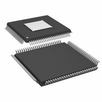
Package / Case
100-TQFP Exposed Pad, 100-eTQFP, 100-HTQFP, 100-VQFP
Format
Fixed Point
Program Memory Size
Not RequiredKB
Operating Supply Voltage (typ)
1.8/3.3V
Operating Temp Range
-40C to 105C
Operating Temperature Classification
Industrial
Mounting
Surface Mount
Pin Count
100
Lead Free Status / RoHS Status
Lead free / RoHS Compliant
Lead Free Status / RoHS Status
Lead free / RoHS Compliant
Available stocks
Company
Part Number
Manufacturer
Quantity
Price
Company:

Part Number:
ADAU1445YSVZ-3A-RL
Manufacturer:
Analog Devices Inc
Quantity:
10 000


MULTIPURPOSE PINS
The ADAU1442/ADAU1445/ADAU1446 each incl
12 multipurpo pins that can b
purpos
au
E
P
ap
cir
o
W
v
th
E
To write a Logic 1, the bytes written should be 0x00, 0x80, 0x00,
and 0x00. To write a Logic 0, the bytes written should be 0x00,
0x00, 0x00, and 0x00.
When the outputs are driven by the core, they are represented
as MP outputs in the SigmaStudio programming tool and are
driven directly from the DSP program in 5.23 format.
In addition, there are 12 multipurpose pin value registers that
allow the input/output data to be written to or read directly
from the control port. The corresponding addresses are listed in
T
st
st
0x00, 0x00, 0x00. The value of the auxiliary ADC is not stored
in these registers. The value of these registers can only be one of
two values: 0x00 0x00 0x00 0x00 (digital zero) or 0x00 0x80
0x00 0x00 (digital one). More information about the
multipurpose pins can be found in the AN-951 Application
Note, Using Hardware Controls with SigmaDSP GPIO Pins .
MULTIPURPOSE PINS MODES AND SETTINGS
Multipurpose Pin Control Registers (Address 0xE204 to
Address 0xE20F)
Table 66. Addresses of Multipurpose Pin Control Registers
Decimal
57860
57861
57862
57863
57864
57865
57866
57867
57868
57869
57870
57871
alue can be dir
ins can be conf
f selectable tim
able 68. Each value register contains four bytes and can only
ach of the 12 m
ach of these registers is four bytes long and is in 5.23 format.
ore one of two values: logic high or logic low. Logic high is
ored as 0x00, 0x80, 0x00, 0x00. Logic low is stored as 0x00,
e addresses lis
xiliary ADC.
plicable, as an
hen the input
cuit is include
Address
e inputs/o
Hex
E204
E205
E206
E207
E208
E209
E20A
E20B
E20C
E20D
E20E
E20F
se
igured as d
ectly read or con
s or outputs are dr
ted in Table 66.
e constants betw
utputs (GP
d for use with d
ultipur
analog input to t
pose pins is controlled by a 4-b mode.
Register
Multipurpose pin control, MP0
Multipurpose pin control, MP1
Multipurpose pin control, MP2
Multipurpose pin control, MP3
Multipurpose pin control, MP4
Multipurpose pin control, MP5
Multipurpose pin control, MP6
Multipurpose pin control, MP7
Multipurpose pin control, MP8
Multipurpose pin control, MP9
Multipurpose pin control, MP10
Multipurpose pin control, MP11
igital inputs, digital outputs, or hen
IOs) or as inputs to the 4-chan el
e used either as digital gen
igital inputs, and it has range
trolled by reading or w ing
een 0.3 μs and 40 μs.
he auxiliary ADC. A d ounce
iven by the control p
ude
it
ort
, w
eral-
rit
a
n
eb
, the
Rev. C | Page 69 of 92
Table 67. Bit Settings of Multipurpose Pin Control Registers
Bit
Position
[15:4]
[3:
Multipurpose Pin Value Registers (Address 0x129A to
Address 0x12A5)
Table 68. Addresses of Multipurpose Pin Value Registers
Dec
4672
4673
4674
4675
4676
4677
4678
4679
4680
4681
4682
4683
0]
Address
Hex
0x1240
0x1241
0x1242
0x1243
0x1244
0x1245
0x1246
0x1247
0x1248
0x1249
0x124A
0x124B
Description
Reserved
MP pin mode
0000 = input without a debounce
0001 = input with a debounce of 0.3 ms
0010 = input with a debounce of 0.6 ms
0011 = input with a debounce of 0.9 ms
0100 = input with a debounce of 5 ms
0101 = input with a debounce of 10 ms
0110 = input with a debounce of 20 ms
0111 = input with a debounce of 40 ms
1000 = input driven by control port
1001 = output driven by control port
with pull-up
1010 =
withou
1011 =
1100 =
pull-up
1101 =
MP3 on
1110 = output CRC error sticky
1111 =
ADAU1442/ADAU1445/ADAU1446
t pull-up
output driven by control port
output driven by core with pull-u
output driven by core without
input auxiliary ADC (MP0 to
ly)
output wa
Register
Multipurpose pin value, MP0
Multipurpose pin value, MP1
Multipurpose pin value, MP2
Multipurpose pin value, MP3
Multipurpose pin value, MP4
Multipurpose pin value, MP5
Multipurpose pin value, MP6
Multipurpose pin value, MP7
Multipurpose pin value, MP8
Multipurpose pin value, MP9
Multipurpose pin value, MP10
Multipurpose pin value, MP11
tchdog error sticky
p
Default
0000
Related parts for ADAU1445YSVZ-3A-RL
Image
Part Number
Description
Manufacturer
Datasheet
Request
R

Part Number:
Description:
SigmaDSP� Digital Audio Processor with Flexible Audio Routing Matrix
Manufacturer:
Analog Devices
Datasheet:

Part Number:
Description:
±1.7g Dual-Axis IMEMS Accelerometer Evaluation Board
Manufacturer:
Analog Devices Inc
Datasheet:

Part Number:
Description:
Inertial Sensor Evaluation System
Manufacturer:
Analog Devices Inc
Datasheet:
Part Number:
Description:
Manufacturer:
Analog Devices Inc
Datasheet:
Part Number:
Description:
Manufacturer:
Analog Devices Inc
Datasheet:
Part Number:
Description:
Manufacturer:
Analog Devices Inc
Datasheet:
Part Number:
Description:
Manufacturer:
Analog Devices Inc
Datasheet:
Part Number:
Description:
Manufacturer:
Analog Devices Inc
Datasheet:
Part Number:
Description:
Manufacturer:
Analog Devices Inc
Datasheet:
Part Number:
Description:
Manufacturer:
Analog Devices Inc
Datasheet:
Part Number:
Description:
Manufacturer:
Analog Devices Inc
Datasheet:
Part Number:
Description:
Manufacturer:
Analog Devices Inc
Datasheet:
Part Number:
Description:
Manufacturer:
Analog Devices Inc
Datasheet: