EVAL-ADF7021-NDBZ2 Analog Devices Inc, EVAL-ADF7021-NDBZ2 Datasheet - Page 17
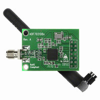
EVAL-ADF7021-NDBZ2
Manufacturer Part Number
EVAL-ADF7021-NDBZ2
Description
860 MHz To 870 MHz
Manufacturer
Analog Devices Inc
Type
Transceiver, FSKr
Datasheet
1.ADF7021-NBCPZ-RL.pdf
(64 pages)
Specifications of EVAL-ADF7021-NDBZ2
Frequency
860MHz ~ 870MHz
Lead Free Status / RoHS Status
Lead free / RoHS Compliant
For Use With/related Products
ADF7021-N
Lead Free Status / RoHS Status
Lead free / RoHS Compliant


Pin No.
29
30
31
32
33
34
35
36
37
38
39
40
41
42
43
44, 46
45, 47
48
Mnemonic
GND2
ADCIN
CREG2
VDD2
SWD
TxRxDATA
TxRxCLK
CLKOUT
MUXOUT
OSC2
OSC1
VDD3
CREG3
CPOUT
VDD
L2, L1
GND, GND1
CVCO
Description
Ground for Digital Section.
Analog-to-Digital Converter Input. The internal 7-bit ADC can be accessed through this pin. Full scale is 0 V to
1.9 V. Readback is made using the SREAD pin.
Regulator Voltage for Digital Block. Place a 100 nF capacitor between this pin and ground for regulator
stability and noise rejection.
Voltage Supply for Digital Block. Place a decoupling capacitor of 10 nF as close as possible to this pin.
Sync Word Detect. The ADF7021-N asserts this pin when it has found a match for the sync word sequence
(see the Register 11—Sync Word Detect Register section). This provides an interrupt for an external
microcontroller indicating that valid data is being received.
Transmit Data Input/Received Data Output. This is a digital pin, and normal CMOS levels apply. In UART/SPI
mode, this pin provides an output for the received data in receive mode. In transmit UART/SPI mode, this pin
is high impedance (see the Interfacing to a Microcontroller/DSP section).
Outputs the data clock in both receive and transmit modes. This is a digital pin, and normal CMOS levels
apply. The positive clock edge is matched to the center of the received data. In transmit mode, this pin
outputs an accurate clock to latch the data from the microcontroller into the transmit section at the exact
required data rate. In UART/SPI mode, this pin is used to input the transmit data in transmit mode. In receive
UART/SPI mode, this pin is high impedance (see the Interfacing to a Microcontroller/DSP section).
A divided-down version of the crystal reference with output driver. The digital clock output can be used to drive
several other CMOS inputs such as a microcontroller clock. The output has a 50:50 mark-space ratio and is inverted
with respect to the reference. Place a series 1 kΩ resistor as close as possible to the pin in applications where the
CLKOUT feature is being used.
Provides the DIGITAL_LOCK_DETECT signal. This signal is used to determine if the PLL is locked to the correct
frequency. It also provides other signals such as REGULATOR_READY, which is an indicator of the status of the
serial interface regulator (see the MUXOUT section for more information).
Connect the reference crystal between this pin and OSC1. A TCXO reference can be used by driving this pin
with CMOS levels and disabling the internal crystal oscillator.
Connect the reference crystal between this pin and OSC2. A TCXO reference can be used by driving this pin
with ac-coupled 0.8 V p-p levels and by enabling the internal crystal oscillator.
Voltage Supply for the Charge Pump and PLL Dividers. Decouple this pin to ground with a 10 nF capacitor.
Regulator Voltage for Charge Pump and PLL Dividers. Place a 100 nF capacitor between this pin and ground
for regulator stability and noise rejection.
Charge Pump Output. This output generates current pulses that are integrated in the loop filter. The
integrated current changes the control voltage on the input to the VCO.
Voltage Supply for VCO Tank Circuit. Decouple this pin to ground with a 10 nF capacitor.
External VCO Inductor Pins. If using an external VCO inductor, connect a chip inductor across these pins to set
the VCO operating frequency. If using the internal VCO inductor, these pins can be left floating. See the
Voltage Controlled Oscillator (VCO) section for more information.
Grounds for VCO Block.
Place a 22 nF capacitor between this pin and CREG1 to reduce VCO noise.
Rev. 0 | Page 17 of 64
ADF7021-N
Related parts for EVAL-ADF7021-NDBZ2
Image
Part Number
Description
Manufacturer
Datasheet
Request
R

Part Number:
Description:
±1.7g Dual-Axis IMEMS Accelerometer Evaluation Board
Manufacturer:
Analog Devices Inc
Datasheet:

Part Number:
Description:
Inertial Sensor Evaluation System
Manufacturer:
Analog Devices Inc
Datasheet:
Part Number:
Description:
Manufacturer:
Analog Devices Inc
Datasheet:
Part Number:
Description:
Manufacturer:
Analog Devices Inc
Datasheet:
Part Number:
Description:
Manufacturer:
Analog Devices Inc
Datasheet:
Part Number:
Description:
Manufacturer:
Analog Devices Inc
Datasheet:
Part Number:
Description:
Manufacturer:
Analog Devices Inc
Datasheet:
Part Number:
Description:
Manufacturer:
Analog Devices Inc
Datasheet:
Part Number:
Description:
Manufacturer:
Analog Devices Inc
Datasheet:
Part Number:
Description:
Manufacturer:
Analog Devices Inc
Datasheet:
Part Number:
Description:
Manufacturer:
Analog Devices Inc
Datasheet:
Part Number:
Description:
Manufacturer:
Analog Devices Inc
Datasheet:
Part Number:
Description:
Manufacturer:
Analog Devices Inc
Datasheet: