EVAL-ADF7021-NDBZ2 Analog Devices Inc, EVAL-ADF7021-NDBZ2 Datasheet - Page 30
EVAL-ADF7021-NDBZ2
Manufacturer Part Number
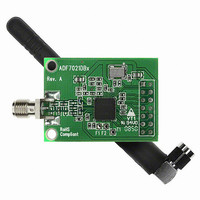
EVAL-ADF7021-NDBZ2
Description
860 MHz To 870 MHz
Manufacturer
Analog Devices Inc
Type
Transceiver, FSKr
Datasheet
1.ADF7021-NBCPZ-RL.pdf
(64 pages)
Specifications of EVAL-ADF7021-NDBZ2
Frequency
860MHz ~ 870MHz
Lead Free Status / RoHS Status
Lead free / RoHS Compliant
For Use With/related Products
ADF7021-N
Lead Free Status / RoHS Status
Lead free / RoHS Compliant


ADF7021-N
RECEIVER SECTION
RF FRONT END
The ADF7021-N is based on a fully integrated, low IF receiver
architecture. The low IF architecture facilitates a very low
external component count and does not suffer from powerline-
induced interference problems.
Figure 45 shows the structure of the receiver front end. The
many programming options allow users to trade off sensitivity,
linearity, and current consumption to best suit their application.
To achieve a high level of resilience against spurious reception,
the low noise amplifier (LNA) features a differential input.
Switch SW2 shorts the LNA input when transmit mode is
selected (R0_DB27 = 0). This feature facilitates the design of a
combined LNA/PA matching network, avoiding the need for an
external Rx/Tx switch. See the LNA/PA Matching section for
details on the design of the matching network.
Tx/Rx SELECT
The LNA is followed by a quadrature downconversion mixer,
which converts the RF signal to the IF frequency of 100 kHz.
An important consideration is that the output frequency of the
synthesizer must be programmed to a value 100 kHz below the
center frequency of the received channel. The LNA has two
basic operating modes: high gain/low noise mode and low
gain/low power mode. To switch between these two modes, use
the LNA_MODE bit (R9_DB25). The mixer is also configurable
between a low current and an enhanced linearity mode using
the MIXER_LINEARITY bit (R9_DB28).
Based on the specific sensitivity and linearity requirements of
the application, it is recommended to adjust the LNA_MODE
bit and MIXER_LINEARITY bit as outlined in Table 15.
The gain of the LNA is configured by the LNA_GAIN bits
(R9_DB[20:21]) and can be set by either the user or the
automatic gain control (AGC) logic.
IF FILTER
IF Filter Settings
Out-of-band interference is rejected by means of a fifth-order
Butterworth polyphase IF filter centered on a frequency of
100 kHz. The bandwidth of the IF filter can be programmed to
9 kHz, 13.5 kHz, or 18.5 kHz by R4_DB[30:31] and should be
LNA/MIXER_ENABLE
(R0_DB27)
(R9_DB[26:27])
(R9_DB[20:21])
RFINB
LNA_MODE
LNA_GAIN
RFIN
(R9_DB25)
LNA_BIAS
(R8_DB6)
SW2
Figure 45. RF Front End
LNA
LO
I (TO FILTER)
Q (TO FILTER)
MIXER LINEARITY
(R9_DB28)
Rev. 0 | Page 30 of 64
chosen as a compromise between interference rejection and
attenuation of the desired signal.
If the AGC loop is disabled, the gain of the IF filter can be set to one
of three levels by using the FILTER_GAIN bits (R9_DB[22:23]).
The filter gain is adjusted automatically if the AGC loop is
enabled.
IF Filter Bandwidth and Center Frequency Calibration
To compensate for manufacturing tolerances, the IF filter should be
calibrated after power-up to ensure that the bandwidth and
center frequency are correct. Coarse and fine calibration
schemes are provided to offer a choice between fast calibration
(coarse calibration) and high filter centering accuracy (fine
calibration). Coarse calibration is enabled by setting R5_DB4
high. Fine calibration is enabled by setting R6_DB4 high.
For details on when it is necessary to perform a filter
calibration, and in what applications to use either a coarse
calibration or fine calibration, refer to the IF Filter Bandwidth
Calibration section.
RSSI/AGC
The RSSI is implemented as a successive compression log amp
following the baseband (BB) channel filtering. The log amp
achieves ±3 dB log linearity. It also doubles as a limiter to
convert the signal-to-digital levels for the FSK demodulator.
The offset correction circuit uses the BBOS_CLK_DIVIDE bits
(R3_DB[4:5]), which should be set between 1 MHz and 2 MHz.
The RSSI level is converted for user readback and for digitally
controlled AGC by an 80-level (7-bit) flash ADC. This level can
be converted to input power in dBm. By default, the AGC is on
when powered up in receive mode.
RSSI Thresholds
When the RSSI is above AGC_HIGH_THRESHOLD
(R9_DB[11:17]), the gain is reduced. When the RSSI is
below AGC_LOW_THRESHOLD (R9_DB[4:10]), the gain
is increased. The thresholds default to 30 and 70 on power-up
in receive mode. A delay (set by AGC_CLK_DIVIDE,
R3_DB[26:31]) is programmed to allow for settling of the loop.
A value of 13 is recommended to give an AGC update rate of
7.7 kHz.
1
IFWR
CORRECTION
A
OFFSET
IFWR
Figure 46. RSSI Block Diagram
Error! Unknown document
A
R
IFWR
A
IFWR
LATCH
property name.
CLK
FSK
DEMOD
ADC
RSSI
Related parts for EVAL-ADF7021-NDBZ2
Image
Part Number
Description
Manufacturer
Datasheet
Request
R

Part Number:
Description:
±1.7g Dual-Axis IMEMS Accelerometer Evaluation Board
Manufacturer:
Analog Devices Inc
Datasheet:

Part Number:
Description:
Inertial Sensor Evaluation System
Manufacturer:
Analog Devices Inc
Datasheet:
Part Number:
Description:
Manufacturer:
Analog Devices Inc
Datasheet:
Part Number:
Description:
Manufacturer:
Analog Devices Inc
Datasheet:
Part Number:
Description:
Manufacturer:
Analog Devices Inc
Datasheet:
Part Number:
Description:
Manufacturer:
Analog Devices Inc
Datasheet:
Part Number:
Description:
Manufacturer:
Analog Devices Inc
Datasheet:
Part Number:
Description:
Manufacturer:
Analog Devices Inc
Datasheet:
Part Number:
Description:
Manufacturer:
Analog Devices Inc
Datasheet:
Part Number:
Description:
Manufacturer:
Analog Devices Inc
Datasheet:
Part Number:
Description:
Manufacturer:
Analog Devices Inc
Datasheet:
Part Number:
Description:
Manufacturer:
Analog Devices Inc
Datasheet:
Part Number:
Description:
Manufacturer:
Analog Devices Inc
Datasheet: