AD9912/PCBZ Analog Devices Inc, AD9912/PCBZ Datasheet - Page 11
AD9912/PCBZ
Manufacturer Part Number
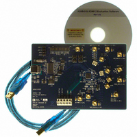
AD9912/PCBZ
Description
Eval Board
Manufacturer
Analog Devices Inc
Series
AgileRF™r
Specifications of AD9912/PCBZ
Kit Features
Flexible System Clock I/P Accepts Crystal
Supported Devices
AD9912
Tool / Board Applications
Direct Digital Synthesizer
Development Tool Type
Hardware - Eval/Demo Board
Mcu Supported Families
AD9912
Main Purpose
Timing, Direct Digital Synthesis (DDS)
Embedded
No
Utilized Ic / Part
AD9912
Primary Attributes
14-Bit DAC, 48-Bit Tuning Word Width
Secondary Attributes
1GHz, Graphical User Interface
Lead Free Status / RoHS Status
Lead free / RoHS Compliant
Lead Free Status / RoHS Status
Lead free / RoHS Compliant, Lead free / RoHS Compliant


AD9912 SYSTEM CLOCK PLL LOOP FILTER
The
components are tailored for different applications.
If the system clock PLL is bypassed, the LOOPFILTER pin
should be pulled down to ground with a 1 kΩ resistor.
The loop bandwidth of the SYSCLK multiplier PLL can be
adjusted by means of three external components, as shown in
Table 1. The nominal gain of the VCO is 800 MHz/V. The
recommended component values and their locations on the
evaluation board are shown in Table 1. They establish a loop
bandwidth of approximately 1.6 MHz with the charge pump
current set to 250 μA. The default case is N = 40 and assumes a
25 MHz SYSCLK input frequency and generates an internal
DAC sampling frequency (f
When modeling the AD9912 system clock PLL, bear in mind
that there is approximately 5 pF of parallel capacitance internal
to Shunt C (C88). The values in Table 1 are the actual values
AD9912
system clock PLL has an external loop filter whose
S
) of 1 GHz.
Rev. 0 | Page 11 of 12
that should be used on the board and do not include this
internal capacitance.
The AD9912 features a bipolar edge detector that doubles the
rate of the clock going into the system clock PLL. The
multiplication factors in Table 1 are for the system clock PLL
only. Refer to the AD9912 data sheet for more details on the
system clock PLL and bipolar edge detector.
Table 1. Recommended SYSCLK PLL Loop Filter Values
SYSCLK
Multiplier
8 (or less)
10
20
40 (default)
60
Series R
(R98)
390 Ω
470 Ω
1 kΩ
2.2 kΩ
2.7 kΩ
Series C
(C83)
1 nF
820 pF
390 pF
180 pF
120 pF
AD9912/PCBZ
Shunt C
(C88)
82 pF
56 pF
27 pF
10 pF
5 pF
Related parts for AD9912/PCBZ
Image
Part Number
Description
Manufacturer
Datasheet
Request
R


Part Number:
Description:
±1.7g Dual-Axis IMEMS Accelerometer Evaluation Board
Manufacturer:
Analog Devices Inc
Datasheet:

Part Number:
Description:
Inertial Sensor Evaluation System
Manufacturer:
Analog Devices Inc
Datasheet:
Part Number:
Description:
Manufacturer:
Analog Devices Inc
Datasheet:
Part Number:
Description:
Manufacturer:
Analog Devices Inc
Datasheet:
Part Number:
Description:
Manufacturer:
Analog Devices Inc
Datasheet:
Part Number:
Description:
Manufacturer:
Analog Devices Inc
Datasheet:
Part Number:
Description:
Manufacturer:
Analog Devices Inc
Datasheet:
Part Number:
Description:
Manufacturer:
Analog Devices Inc
Datasheet:
Part Number:
Description:
Manufacturer:
Analog Devices Inc
Datasheet:
Part Number:
Description:
Manufacturer:
Analog Devices Inc
Datasheet:
Part Number:
Description:
Manufacturer:
Analog Devices Inc
Datasheet:
Part Number:
Description:
Manufacturer:
Analog Devices Inc
Datasheet: