AD9912/PCBZ Analog Devices Inc, AD9912/PCBZ Datasheet - Page 7
AD9912/PCBZ
Manufacturer Part Number
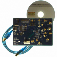
AD9912/PCBZ
Description
Eval Board
Manufacturer
Analog Devices Inc
Series
AgileRF™r
Specifications of AD9912/PCBZ
Kit Features
Flexible System Clock I/P Accepts Crystal
Supported Devices
AD9912
Tool / Board Applications
Direct Digital Synthesizer
Development Tool Type
Hardware - Eval/Demo Board
Mcu Supported Families
AD9912
Main Purpose
Timing, Direct Digital Synthesis (DDS)
Embedded
No
Utilized Ic / Part
AD9912
Primary Attributes
14-Bit DAC, 48-Bit Tuning Word Width
Secondary Attributes
1GHz, Graphical User Interface
Lead Free Status / RoHS Status
Lead free / RoHS Compliant
Lead Free Status / RoHS Status
Lead free / RoHS Compliant, Lead free / RoHS Compliant


I/O Menu
Select Evaluation Board
The AD9912 evaluation system allows one PC to control
multiple evaluation boards. This command allows the user to
select which evaluation board the software controls.
DUT I/O Configure
This command selects 3- or 4-wire serial port mode, LSB first,
and contains a button for a soft I/O reset.
Window Menu
This menu allows the user to select any of the 14 windows that
are associated with the major functional blocks of the AD9912.
These windows are also accessible by going to the Interactive
Block Diagram window and clicking the block of interest. See
the Evaluation Software Functional Blocks section for a
description of each of these windows.
Help Menu
Selecting Help brings up the About AD9912 splash screen. It
contains information such as revision number, region informa-
tion, and contact information.
Rev. 0 | Page 7 of 12
BUTTON BAR
The following buttons are provided for easy access to common
features.
Load Eval Board Setup/Save Eval Board Setup
These buttons allow the user load/save a AD9912 setup file
(.STP). A setup file is a text file that contains the AD9912
register setup file, plus any evaluation board settings.
Note that when saving register setup files, it is important to
select single-tone mode before saving the file. Register setup
files are loaded into the AD9912 sequentially, and the loop
should only be locked once all registers are loaded. Otherwise,
the part may need to be reset.
Reset
This button resets the evaluation board and restores the
AD9912 to its default power-up state.
I/O Update
This button toggles the IO_UPDATE pin on the AD9912.
Block Diagram
This button selects the Interactive Block Diagram window.
Debug Window
This button selects the Debug window. See the Debug Window
section for a description.
AD9912/PCBZ
Related parts for AD9912/PCBZ
Image
Part Number
Description
Manufacturer
Datasheet
Request
R


Part Number:
Description:
±1.7g Dual-Axis IMEMS Accelerometer Evaluation Board
Manufacturer:
Analog Devices Inc
Datasheet:

Part Number:
Description:
Inertial Sensor Evaluation System
Manufacturer:
Analog Devices Inc
Datasheet:
Part Number:
Description:
Manufacturer:
Analog Devices Inc
Datasheet:
Part Number:
Description:
Manufacturer:
Analog Devices Inc
Datasheet:
Part Number:
Description:
Manufacturer:
Analog Devices Inc
Datasheet:
Part Number:
Description:
Manufacturer:
Analog Devices Inc
Datasheet:
Part Number:
Description:
Manufacturer:
Analog Devices Inc
Datasheet:
Part Number:
Description:
Manufacturer:
Analog Devices Inc
Datasheet:
Part Number:
Description:
Manufacturer:
Analog Devices Inc
Datasheet:
Part Number:
Description:
Manufacturer:
Analog Devices Inc
Datasheet:
Part Number:
Description:
Manufacturer:
Analog Devices Inc
Datasheet:
Part Number:
Description:
Manufacturer:
Analog Devices Inc
Datasheet: