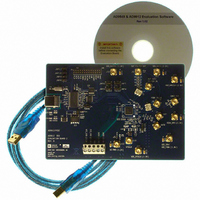
AD9912/PCBZ Analog Devices Inc, AD9912/PCBZ Datasheet - Page 9

AD9912/PCBZ
Manufacturer Part Number
AD9912/PCBZ
Description
Eval Board
Manufacturer
Analog Devices Inc
Series
AgileRF™r
Specifications of AD9912/PCBZ
Kit Features
Flexible System Clock I/P Accepts Crystal
Supported Devices
AD9912
Tool / Board Applications
Direct Digital Synthesizer
Development Tool Type
Hardware - Eval/Demo Board
Mcu Supported Families
AD9912
Main Purpose
Timing, Direct Digital Synthesis (DDS)
Embedded
No
Utilized Ic / Part
AD9912
Primary Attributes
14-Bit DAC, 48-Bit Tuning Word Width
Secondary Attributes
1GHz, Graphical User Interface
Lead Free Status / RoHS Status
Lead free / RoHS Compliant
Lead Free Status / RoHS Status
Lead free / RoHS Compliant, Lead free / RoHS Compliant
AD9912 EVALUATION BOARD RECONSTRUCTION FILTER
Revision A of the
low-pass reconstruction filter that is shown in Figure 4.
Revision B has a 400 MHz low-pass reconstruction filter. This
filter is implemented as a single-ended filter with a transformer
on both sides to convert to/from a differential configuration.
The transformer used is a Mini-Circuits ADTT-1, and its −3 dB
bandwidth is approximately 0.3 MHz to 300 MHz.
SINGLE-ENDED FILTER DESIGN
The single-ended design with transformers is less susceptible to
component variation and is strongly recommended for cases
where the cutoff frequency must be tightly controlled, or in
designs using a pass-band reconstruction filter. See the AD9912
evaluation board schematic for the exact circuit implementation.
7
•
•
•
•
•
th
Order Single-Ended Low-Pass Elliptical Filter (Rev. A)
Pass-band frequency: 240 MHz
Pass-band ripple: 0.1 dB
Stop-band ratio: 1.3
Stop-band frequency: 312 MHz
Stop-band attenuation: 60 dB
AD9912
EQUIVALENT CIRCUIT
FOR AD9912 AND
TRANSFORMER
evaluation board has a 240 MHz
–10
–20
–30
–40
–50
–60
–70
–80
0
10M
R1
50.0Ω
Figure 5. Frequency Response of Single-Ended Reconstruction Filter Shown in Figure 4
Figure 4. AD9912 Evaluation Board 240 MHz Single-Ended Reconstruction Filter
C2
9.0pF
310MHz
PHASE
L3
27.0nH
C3
9.70pF
C4
20.0pF
Rev. 0 | Page 9 of 12
370MHz
L5
39.0nH
C5
4.70pF
FREQUENCY (Hz)
100M
Location of Filter Components on Evaluation Board
Note that when the on-board reconstruction filter is bypassed,
R12 is removed. R13 is installed and the output is on Connector J4.
The following values are for the 240 MHz reconstruction filter:
•
•
•
•
•
•
•
C6
23.0pF
610MHz
9 pF shunt capacitor: C11 = 4.7 pF in parallel with
C80 = 4.7 pF
20 pF shunt capacitor: C4 = 10 pF in parallel with
C36 = 10 pF
23 pF shunt capacitor: C2 = 12 pF in parallel with
C28 = 12 pF
14 pF shunt capacitor: C3 = 6.8 pF in parallel with
C14 = 6.8 pF
1
2
3
L7
47.0nH
C7
1.50pF
st
nd
rd
LC combination: C1 = 8.2 pF, L3 = 27 nH
LC combination: C5 = 1.5 pF, L1 = 47 nH
LC combination: C10 = 4.7 pF, L2 = 39 nH
MAGNITUDE
C8
14.0pF
EQUIVALENT CIRCUIT
AND AD9912 FDBK_IN
FOR TRANSFORMER,
IMPEDANCE MATCH,
R9
50.0Ω
1G
200
150
100
50
0
–50
–100
–150
–200
AD9912/PCBZ


