AD9912/PCBZ Analog Devices Inc, AD9912/PCBZ Datasheet - Page 5
AD9912/PCBZ
Manufacturer Part Number
AD9912/PCBZ
Description
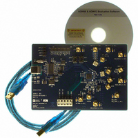
Eval Board
Manufacturer
Analog Devices Inc
Series
AgileRF™r
Specifications of AD9912/PCBZ
Kit Features
Flexible System Clock I/P Accepts Crystal
Supported Devices
AD9912
Tool / Board Applications
Direct Digital Synthesizer
Development Tool Type
Hardware - Eval/Demo Board
Mcu Supported Families
AD9912
Main Purpose
Timing, Direct Digital Synthesis (DDS)
Embedded
No
Utilized Ic / Part
AD9912
Primary Attributes
14-Bit DAC, 48-Bit Tuning Word Width
Secondary Attributes
1GHz, Graphical User Interface
Lead Free Status / RoHS Status
Lead free / RoHS Compliant
Lead Free Status / RoHS Status
Lead free / RoHS Compliant, Lead free / RoHS Compliant


EVALUATION BOARD SOFTWARE SETUP
The following instructions are for setting up the
evaluation board software. The same software can be used for
both Revision A and Revision B of the AD9912 evaluation board.
The following case is used as an example: output frequency:
155.52 MHz; DAC system clock: 1000 MHz input provided on
the SYSCLK SMA connector; system clock PLL is disabled.
SOFTWARE INSTALLATION
1.
2.
3.
4.
5.
RUNNING THE SOFTWARE
1.
2.
3.
4.
Insert the AD9912 Evaluation Software CD-ROM.
A window will open showing the contents of the CD
divided into three sections: Layout, Schematic, and
Software.
Double-click the Software folder.
Double-click AD9549_9912setup.exe.
Follow the installation instructions.
The default location for the evaluation software is
C:\Program Files\ADI\AD9549_9912 Eval Software.
If there are any updates to the evaluation software on a
supplemental CD, be sure to copy the new .exe file, as well
as any setup files to the above location.
If you have not connected your evaluation board yet, refer
to the Evaluation Board Physical Connections section.
Double-click AD9549 & AD9912 Evaluation Software.
Run the AD9912 evaluation software, and click the splash
screen when the Software Ready message is displayed. You
will see the Interactive Block Diagram window, which is
the main window for the software.
If you have not yet connected your evaluation board, you
will be prompted to choose AD9912 or AD9549 evaluation
board. Click AD9912 Evaluation Board.
Note that Windows will indicate Found New Hardware
the first time you connect the evaluation board. Nothing
AD9912
Rev. 0 | Page 5 of 12
5.
6.
7.
8.
9.
10. If the CMOS driver is not being used, it can be powered
See the Evaluation Software Main Window section for a
description of the main window features, or see the Evaluation
Software Functional Blocks section for details on the individual
blocks of the AD9912.
special needs to be done when this happens, and Windows
will install the software driver. It may be necessary to
disconnect and reconnect the USB cable after this happens.
In the lower left corner of the window, look for Ezssp-0,
Ezssp-1, or Ezssp-2 in green letters. This indicates that the
software has found and connected to the evaluation board.
If you see not connected, the software cannot locate the
evaluation board. Try selecting Select Evaluation Board
from the I/O menu and see if Ezssp-0, Ezssp-1, or Ezssp-2
can be selected. If not, check your cable connections,
power cycle the board, and rerun the software to remedy
this problem.
The main window is the Interactive Block Diagram
window. Click the Reset button at the top of the
Interactive Block Diagram window.
If you have a setup file, click Load Eval Board Setup at the
top of the window and select the desired setup .STP file.
If the reference frequency that is provided to the system
clock input is different from 25 MHz, click the DDS box,
and enter the frequency in the External Clock box. This is
critical because the evaluation software relies on the
correct system clock in order to calculate the various
frequencies used on the AD9912.
You should now see the 155.52 MHz output. If HSTL
output on Connector J1 and Connector J2 are desired,
enable the 1.8 V HSTL driver by clicking the triangle inside
the dashed box in the Interactive Block Diagram window.
down by clicking the triangle inside the dashed box in the
Interactive Block Diagram window.
AD9912/PCBZ
Related parts for AD9912/PCBZ
Image
Part Number
Description
Manufacturer
Datasheet
Request
R


Part Number:
Description:
±1.7g Dual-Axis IMEMS Accelerometer Evaluation Board
Manufacturer:
Analog Devices Inc
Datasheet:

Part Number:
Description:
Inertial Sensor Evaluation System
Manufacturer:
Analog Devices Inc
Datasheet:
Part Number:
Description:
Manufacturer:
Analog Devices Inc
Datasheet:
Part Number:
Description:
Manufacturer:
Analog Devices Inc
Datasheet:
Part Number:
Description:
Manufacturer:
Analog Devices Inc
Datasheet:
Part Number:
Description:
Manufacturer:
Analog Devices Inc
Datasheet:
Part Number:
Description:
Manufacturer:
Analog Devices Inc
Datasheet:
Part Number:
Description:
Manufacturer:
Analog Devices Inc
Datasheet:
Part Number:
Description:
Manufacturer:
Analog Devices Inc
Datasheet:
Part Number:
Description:
Manufacturer:
Analog Devices Inc
Datasheet:
Part Number:
Description:
Manufacturer:
Analog Devices Inc
Datasheet:
Part Number:
Description:
Manufacturer:
Analog Devices Inc
Datasheet: