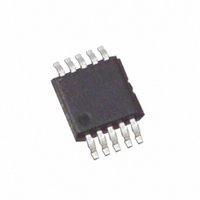
ISL95311UIU10Z-TK Intersil, ISL95311UIU10Z-TK Datasheet - Page 10

ISL95311UIU10Z-TK
Manufacturer Part Number
ISL95311UIU10Z-TK
Description
IC XDCP 128-TAP 50KOHM 10-MSOP
Manufacturer
Intersil
Series
XDCP™r
Datasheet
1.ISL95311WIU10Z-TK.pdf
(11 pages)
Specifications of ISL95311UIU10Z-TK
Taps
128
Resistance (ohms)
50K
Number Of Circuits
1
Temperature Coefficient
45 ppm/°C Typical
Memory Type
Non-Volatile
Interface
I²C, 2-Wire Serial
Voltage - Supply
2.7 V ~ 5.5 V
Operating Temperature
-40°C ~ 85°C
Mounting Type
Surface Mount
Package / Case
10-MSOP, Micro10™, 10-uMAX, 10-uSOP
Resistance In Ohms
50K
Lead Free Status / RoHS Status
Lead free / RoHS Compliant
Communicating with the ISL95311
There are 3 register addresses in the ISL95311, of which two
can be used. Address 00h and address 02h are used to
control the device. Address 01h is reserved and should not
be used. Address 00h contains the nonvolatile Initial Value
Register (IVR), and the volatile Wiper Register (WR).
Address 02h contains only a volatile word and is used as a
pointer to either the IVR or WR. See Table 1.
Register Descriptions: Access Control
The Access Control Register (ACR) is volatile and is at
address 02h. It is 8-bits, and only the MSB is significant, all
other bits should be zero (0). The ACR controls which word
is accessed at register 00h as follows:
00h = Nonvolatile IVR
80h = Volatile WR
All other bits of the ACR should be written to as zeros. Only
the MSB can be either 0 or 1. Power-up default for this
address is 00h.
Example 1
WRITING A NEW VALUE (77H) TO THE IVR:
(Note that the WR will also reflect this new value since both registers get written to at the same time)
Example 2
READING FROM THE WR:
Notes: A = acknowledge, x = data bit read
Write to ACR first
Then, write to IVR
Write to the ACR first (to index the WR)
Then, Set the WR address
Read from the WR
0
0
0
0
0
1
1
1
1
1
0
0
0
0
0
1
1
1
1
1
10
0
0
0
0
0
0
0
0
0
0
0
0
0
0
0
0
0
0
0
1
A
A
A
A
A
0
0
0
0
x
0
0
0
0
x
0
0
0
0
x
ISL95311
0
0
0
0
x
0
0
0
0
x
0
0
0
0
x
Register Description: IVR and WR
The ISL95311 has a single potentiometer. The wiper of the
potentiometer is controlled directly by the WR. Writes and
reads can be made directly to this register to control and
monitor the wiper position without any nonvolatile memory
changes. This is done by setting address 02h to data 80h,
then writing the data.
The nonvolatile IVR stores the power-up value of the wiper.
On power-up, the contents of the IVR are transferred to the
WR.
To write to the IVR, first address 02h is set to data 00h, then
the data is written. Writing a new value to the IVR register
will set a new power-up position for the wiper. Also, writing to
this register will load the same value into the WR as the IVR.
So, if a new value is loaded into the IVR, not only will the
non-volatile IVR change, but the WR will also contain the
same value after the write, and the wiper position will
change. Reading from the IVR will not change the WR, if its
contents are different.
1
0
1
0
x
0
0
0
0
x
A
A
A
A
0
0
0
0
1
0
0
1
0
0
1
0
0
0
0
0
1
0
0
1
1
0
1
0
A
A
A
February 6, 2008
FN8084.1


