XPC8240RZU250E Freescale Semiconductor, XPC8240RZU250E Datasheet - Page 15
XPC8240RZU250E
Manufacturer Part Number
XPC8240RZU250E
Description
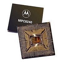
MCU HOST PROCESSOR 352-TBGA
Manufacturer
Freescale Semiconductor
Series
PowerQUICC IIr
Specifications of XPC8240RZU250E
Processor Type
MPC82xx PowerQUICC II 32-bit
Speed
200MHz
Voltage
2.5V
Mounting Type
Surface Mount
Package / Case
352-TBGA
Core Size
32 Bit
Program Memory Size
32KB
Cpu Speed
250MHz
Embedded Interface Type
I2C
Digital Ic Case Style
TBGA
No. Of Pins
352
Supply Voltage Range
2.5V To 2.75V
Rohs Compliant
No
Family Name
MPC82XX
Device Core Size
32b
Frequency (max)
250MHz
Instruction Set Architecture
RISC
Supply Voltage 1 (typ)
2.625/2.6255V
Operating Supply Voltage (max)
2.75625/2.756775V
Operating Supply Voltage (min)
2.49375/2.494225V
Operating Temp Range
0C to 105C
Operating Temperature Classification
Commercial
Mounting
Surface Mount
Pin Count
352
Package Type
TBGA
Lead Free Status / RoHS Status
Contains lead / RoHS non-compliant
Features
-
Lead Free Status / Rohs Status
Not Compliant
Available stocks
Company
Part Number
Manufacturer
Quantity
Price
Company:

Part Number:
XPC8240RZU250E
Manufacturer:
MOT
Quantity:
12 388
Company:
Part Number:
XPC8240RZU250E
Manufacturer:
MOTOLOLA
Quantity:
513
Company:
Part Number:
XPC8240RZU250E
Manufacturer:
Freescale Semiconductor
Quantity:
10 000
Part Number:
XPC8240RZU250E
Manufacturer:
FREESCALE
Quantity:
20 000


MPC8240 Integrated Processor Hardware Specifications
At recommended operating conditions (see Table 2) with LV
Notes:
1. All memory and related interface input signal specifications are measured from the TTL level (0.8 or 2.0 V) of the
2. All PCI signals are measured from OV
3. Input timings are measured at the pin.
4. t
5. All mode select input signals specifications are measured from the TTL level (0.8 or 2.0 V) of the signal in question
Num
11a
11b
signal in question to the VM = 1.4 V of the rising edge of the memory bus clock, SDRAM_SYNC_IN.
SDRAM_SYNC_IN is the same as PCI_SYNC_IN in 1:1 mode, but is twice the frequency in 2:1 mode
(processor/memory bus clock rising edges occur on every rising and falling edge of PCI_SYNC_IN). See Figure 8.
question for 3.3-V PCI signaling levels. See Figure 9.
to the VM = 1.4 V of the rising edge of the HRST_CPU/HRST_CTRL signal. See Figure 10.
CLK
SDRAM_SYNC_IN
Shown in 2:1 Mode
PCI_SYNC_IN
Inputs/Outputs
PCI_SYNC_IN (SDRAM_SYNC_IN) to inputs invalid (input hold)
HRST_CPU/HRST_CTRL to mode select inputs invalid (input hold)
is the time of one SDRAM_SYNC_IN clock cycle.
PCI_SYNC_IN
Inputs/Outputs
MEMORY
Figure 8. Input-Output Timing Diagram Referenced to SDRAM_SYNC_IN
PCI
Figure 9. Input-Output Timing Diagram Referenced to PCI_SYNC_IN
10a
10b-d
Table 8. Input AC Timing Specifications (continued)
Freescale Semiconductor, Inc.
Input Timing
Input Timing
For More Information On This Product,
0.4 × OV
Characteristic
OV
DD
DD
VM
VM
Go to: www.freescale.com
DD
/2 of the rising edge of PCI_SYNC_IN to 0.4 × OV
÷ 2
11a
VM = Midpoint Voltage (1.4 V)
11a
2.0 V
0.8 V
DD
= 3.3 V ± 0.3 V
OV
2.0 V
0.8 V
VM
12a
12b-d
DD
Electrical and Thermal Characteristics
÷ 2
Output Timing
Min
1.0
0
Output Timing
0.615 × OV
0.285 × OV
14a
13a
13b
14b
DD
DD
Max
—
—
DD
OV
VM
of the signal in
DD
÷ 2
Unit
ns
ns
Notes
1, 3, 5
1, 2, 3
15
Related parts for XPC8240RZU250E
Image
Part Number
Description
Manufacturer
Datasheet
Request
R

Part Number:
Description:
Manufacturer:
Freescale Semiconductor, Inc
Datasheet:
Part Number:
Description:
Manufacturer:
Freescale Semiconductor, Inc
Datasheet:
Part Number:
Description:
Manufacturer:
Freescale Semiconductor, Inc
Datasheet:
Part Number:
Description:
Manufacturer:
Freescale Semiconductor, Inc
Datasheet:
Part Number:
Description:
Manufacturer:
Freescale Semiconductor, Inc
Datasheet:
Part Number:
Description:
Manufacturer:
Freescale Semiconductor, Inc
Datasheet:
Part Number:
Description:
Manufacturer:
Freescale Semiconductor, Inc
Datasheet:
Part Number:
Description:
Manufacturer:
Freescale Semiconductor, Inc
Datasheet:
Part Number:
Description:
Manufacturer:
Freescale Semiconductor, Inc
Datasheet:
Part Number:
Description:
Manufacturer:
Freescale Semiconductor, Inc
Datasheet:
Part Number:
Description:
Manufacturer:
Freescale Semiconductor, Inc
Datasheet:
Part Number:
Description:
Manufacturer:
Freescale Semiconductor, Inc
Datasheet:
Part Number:
Description:
Manufacturer:
Freescale Semiconductor, Inc
Datasheet:
Part Number:
Description:
Manufacturer:
Freescale Semiconductor, Inc
Datasheet:
Part Number:
Description:
Manufacturer:
Freescale Semiconductor, Inc
Datasheet: