XPC8240RZU250E Freescale Semiconductor, XPC8240RZU250E Datasheet - Page 46
XPC8240RZU250E
Manufacturer Part Number
XPC8240RZU250E
Description
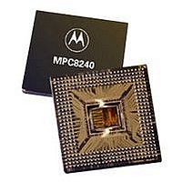
MCU HOST PROCESSOR 352-TBGA
Manufacturer
Freescale Semiconductor
Series
PowerQUICC IIr
Specifications of XPC8240RZU250E
Processor Type
MPC82xx PowerQUICC II 32-bit
Speed
200MHz
Voltage
2.5V
Mounting Type
Surface Mount
Package / Case
352-TBGA
Core Size
32 Bit
Program Memory Size
32KB
Cpu Speed
250MHz
Embedded Interface Type
I2C
Digital Ic Case Style
TBGA
No. Of Pins
352
Supply Voltage Range
2.5V To 2.75V
Rohs Compliant
No
Family Name
MPC82XX
Device Core Size
32b
Frequency (max)
250MHz
Instruction Set Architecture
RISC
Supply Voltage 1 (typ)
2.625/2.6255V
Operating Supply Voltage (max)
2.75625/2.756775V
Operating Supply Voltage (min)
2.49375/2.494225V
Operating Temp Range
0C to 105C
Operating Temperature Classification
Commercial
Mounting
Surface Mount
Pin Count
352
Package Type
TBGA
Lead Free Status / RoHS Status
Contains lead / RoHS non-compliant
Features
-
Lead Free Status / Rohs Status
Not Compliant
Available stocks
Company
Part Number
Manufacturer
Quantity
Price
Company:

Part Number:
XPC8240RZU250E
Manufacturer:
MOT
Quantity:
12 388
Company:
Part Number:
XPC8240RZU250E
Manufacturer:
MOTOLOLA
Quantity:
513
Company:
Part Number:
XPC8240RZU250E
Manufacturer:
Freescale Semiconductor
Quantity:
10 000
Part Number:
XPC8240RZU250E
Manufacturer:
FREESCALE
Quantity:
20 000


Document Revision History
Document Revision History
46
Revision
Number
0.3
0.4
Removed “PowerPC Platform compliant” from first sentence on cover sheet.
Changed PCI 2.1—’compatible’ to ‘compliant’ in Section 1.2.
Updated Table 5 and its notes with preliminary power-consumption information.
Updated Table 6, removing 266 MHz frequency information.
Made corrections to Table 7.
Table 9:
Table 11, item 2, “KAHLUA” terminology replaced with MPC8240.
Added EPIC Serial Interrupt Timing Section with two new figures, causing cross-references to
subsequent figures to be updated.
Updated formatting of pin out in Table 17.
Modified notes section in Table 17:
Figure 18:
Added missing cross-reference in Section 1.7.2 and corrected Schottky reference to the 1N5820 diodes.
Added Section 1.7.2 on power supply sizing.
Modified internal pull-up resistor list in Section 1.7.5 to be consistent with Notes of Table 17; added reset
configuration pin pull-down resistor value recommendation.
Modified Figure 23, COP connector diagram:
Changed R-spec device’s V
Modified DLL Lock Range with DLL_EXTEND = 1 equation in Table 7 from 0
to 0
Modified Figure 5 to only show T
Modified DL[0:31] and DH[0:31] signal names to MDL[0:31] and MDH[0:31], respectively, in Table 17 to
be consistent with the Tundra Tsi107™ PowerPC host bridge data bus naming convention.
Several active low signal names in Table 17 inadvertently had the overline formatting removed during the
final edit process of the previous revision. The signals are shown correctly with overlines in this version.
Signals affected were: DEVSEL, FRAME, LOCK, PERR, SERR, STOP, TRDY, INTA, FOE, RCS0, RCS1,
SDRAS, SDCAS, WE, AS, HRST_CTRL, HRST_CPU, MCP, SMI, SRESET, CHKSTOP_IN, and MIV.
• Items 5a and 5b were changed to correct values for 66-MHz PCI_SYNC_IN.
• OSC_IN Frequency Stability spec from 1000 to 100 ppm.
• Changed item 12b1 from 8.0 to 7.0 ns.
• Added item 12b3, Output Valid for ROM accesses.
• Split Note 3 into new Notes 3 and 12. Notes 3, 5, and 7 cover internal pull-up resistors active only
• Note 11 has been revised.
• Added Note 10 to SDA and SCL signals for consistency with theMPC8240 User’s Manual.
• Added Note 10 to SMI and TBEN; inputs that should have pull-ups and for consistency with reference
• Added Note 10 to SRESET and CHKSTOP_IN for consistency with Figure 23 (COP Connector)
• Added Notes 13 and 14 for output valid specifications dependent upon memory mode.
• Added Note 15 for pins affected by programmable PCI output valid and hold time.
• Added Notes 16 –18 relating to open drain pins.
• Revised 200-MHz column to reflect PCI_SYNC_IN 66-MHz upper limit.
• Refs 1E and 1F not usable entries made to match others in the table.
• Revised Notes 4 and 5 changing OSC_IN to PCI_SYNC_IN.
• Removed 266-MHz column.
• Removed Ref 0x06 for dual PLL bypass mode; added it to reserved list in Note 3.
• Revised Note 4 describing PLL bypass mode.
• Reversed direction of CKSTP_IN arrow to show it going in.
• Added a pull-up resistor on TRST.
during the reset state. Note 12 covers internal pull-up resistors enabled at all times.
designs.
≤
(NT
clk
MPC8240 Integrated Processor Hardware Specifications
– T
clk
Table 19. Document Revision History (continued)
/2 – t
Freescale Semiconductor, Inc.
For More Information On This Product,
loop
– t
DD
fix0
Go to: www.freescale.com
range from 2.5–2.625 V to 2.5–2.75 V.
)
loop
≤
7.
up to 15 ns, not practical to implement T
Substantive Change(s)
≤
loop
(NT
beyond 15 ns.
clk
/2 – t
loop
– t
fix0
)
≤
7
Related parts for XPC8240RZU250E
Image
Part Number
Description
Manufacturer
Datasheet
Request
R

Part Number:
Description:
Manufacturer:
Freescale Semiconductor, Inc
Datasheet:
Part Number:
Description:
Manufacturer:
Freescale Semiconductor, Inc
Datasheet:
Part Number:
Description:
Manufacturer:
Freescale Semiconductor, Inc
Datasheet:
Part Number:
Description:
Manufacturer:
Freescale Semiconductor, Inc
Datasheet:
Part Number:
Description:
Manufacturer:
Freescale Semiconductor, Inc
Datasheet:
Part Number:
Description:
Manufacturer:
Freescale Semiconductor, Inc
Datasheet:
Part Number:
Description:
Manufacturer:
Freescale Semiconductor, Inc
Datasheet:
Part Number:
Description:
Manufacturer:
Freescale Semiconductor, Inc
Datasheet:
Part Number:
Description:
Manufacturer:
Freescale Semiconductor, Inc
Datasheet:
Part Number:
Description:
Manufacturer:
Freescale Semiconductor, Inc
Datasheet:
Part Number:
Description:
Manufacturer:
Freescale Semiconductor, Inc
Datasheet:
Part Number:
Description:
Manufacturer:
Freescale Semiconductor, Inc
Datasheet:
Part Number:
Description:
Manufacturer:
Freescale Semiconductor, Inc
Datasheet:
Part Number:
Description:
Manufacturer:
Freescale Semiconductor, Inc
Datasheet:
Part Number:
Description:
Manufacturer:
Freescale Semiconductor, Inc
Datasheet: