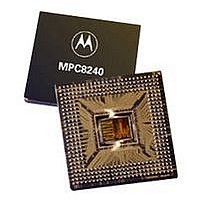
XPC8240RZU250E Freescale Semiconductor, XPC8240RZU250E Datasheet - Page 22

XPC8240RZU250E
Manufacturer Part Number
XPC8240RZU250E
Description
MCU HOST PROCESSOR 352-TBGA
Manufacturer
Freescale Semiconductor
Series
PowerQUICC IIr
Specifications of XPC8240RZU250E
Processor Type
MPC82xx PowerQUICC II 32-bit
Speed
200MHz
Voltage
2.5V
Mounting Type
Surface Mount
Package / Case
352-TBGA
Core Size
32 Bit
Program Memory Size
32KB
Cpu Speed
250MHz
Embedded Interface Type
I2C
Digital Ic Case Style
TBGA
No. Of Pins
352
Supply Voltage Range
2.5V To 2.75V
Rohs Compliant
No
Family Name
MPC82XX
Device Core Size
32b
Frequency (max)
250MHz
Instruction Set Architecture
RISC
Supply Voltage 1 (typ)
2.625/2.6255V
Operating Supply Voltage (max)
2.75625/2.756775V
Operating Supply Voltage (min)
2.49375/2.494225V
Operating Temp Range
0C to 105C
Operating Temperature Classification
Commercial
Mounting
Surface Mount
Pin Count
352
Package Type
TBGA
Lead Free Status / RoHS Status
Contains lead / RoHS non-compliant
Features
-
Lead Free Status / Rohs Status
Not Compliant
Available stocks
Company
Part Number
Manufacturer
Quantity
Price
Company:
Part Number:
XPC8240RZU250E
Manufacturer:
MOT
Quantity:
12 388
Company:
Part Number:
XPC8240RZU250E
Manufacturer:
MOTOLOLA
Quantity:
513
Company:
Part Number:
XPC8240RZU250E
Manufacturer:
Freescale Semiconductor
Quantity:
10 000
Part Number:
XPC8240RZU250E
Manufacturer:
FREESCALE
Quantity:
20 000
Electrical and Thermal Characteristics
Electrical and Thermal Characteristics
Figure 13 through Figure 16 show I
22
At recommended operating conditions (see Table 2) with LV
Notes:
1. Units for these specifications are in SDRAM_CLK units.
2. The actual values depend on the setting of the digital filter frequency sampling rate (DFFSR) bits in the frequency
3. Since SCL and SDA are open-drain type outputs, which the MPC8240 can only drive low, the time required for SCL
4. Specified at a nominal 50-pF load.
5. D
Num
9
divider register I2CFDR. Therefore, the noted timings in this table are all relative to qualified signals. The qualified
SCL and SDA are delayed signals from what is seen in real time on the I
are delayed by the SDRAM_CLK clock times DFFSR times two plus one SDRAM_CLK clock. The resulting delay
value is added to the value in the table (where this note is referenced). See Figure 14.
or SDA to reach a high level depends on external signal capacitance and pull-up resistor values.
clock frequency divider selections table. FDR[n] refers to the frequency divider register I2CFDR bit n. N is equal to
a variable number that would make the result of the divide (data hold time value) equal to a number less than 16.
M is equal to a variable number that would make the result of the divide (data hold time value) equal to a number
less than 9.
FDR
Stop condition setup time
is the decimal divider number indexed by the value of FDR[5:0]. Refer to the I
SCL
SDA
SCL
SDA
Characteristic
VM
VM
Table 13. I
MPC8240 Integrated Processor Hardware Specifications
1
8
5
Freescale Semiconductor, Inc.
For More Information On This Product,
2
C Output AC Timing Specifications (continued)
2
Figure 14. I
Figure 13. I
C timings.
2
Go to: www.freescale.com
V
VM
V
L
H
3
2
DD
2
C Timing Diagram II
6
4
C Timing Diagram I
= 3.3 V ± 0.3 V
Min
4.0
2
C bus. The qualified SCL and SDA signals
9
2
C Interface chapter’s serial bit
Max
—
CLKs
Unit
Notes
1, 2


