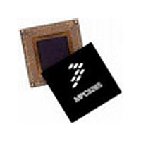
MPC8255ACZUMHBB Freescale Semiconductor, MPC8255ACZUMHBB Datasheet - Page 16

MPC8255ACZUMHBB
Manufacturer Part Number
MPC8255ACZUMHBB
Description
IC MPU POWERQUICC II 480-TBGA
Manufacturer
Freescale Semiconductor
Specifications of MPC8255ACZUMHBB
Processor Type
MPC82xx PowerQUICC II 32-bit
Speed
266MHz
Voltage
2V
Mounting Type
Surface Mount
Package / Case
480-TBGA
Family Name
MPC82XX
Device Core
PowerQUICC II
Device Core Size
32b
Frequency (max)
266MHz
Instruction Set Architecture
RISC
Supply Voltage 1 (typ)
2V
Operating Supply Voltage (max)
2.1V
Operating Supply Voltage (min)
1.9V
Operating Temp Range
-40C to 105C
Operating Temperature Classification
Industrial
Mounting
Surface Mount
Pin Count
480
Package Type
TBGA
Lead Free Status / RoHS Status
Contains lead / RoHS non-compliant
Features
-
Lead Free Status / Rohs Status
Not Compliant
Available stocks
Company
Part Number
Manufacturer
Quantity
Price
Company:
Part Number:
MPC8255ACZUMHBB
Manufacturer:
MOTOROLA
Quantity:
745
Company:
Part Number:
MPC8255ACZUMHBB
Manufacturer:
Freescale Semiconductor
Quantity:
10 000
Part Number:
MPC8255ACZUMHBB
Manufacturer:
FREESCALE
Quantity:
20 000
Clock Configuration Modes
1.3
To configure the main PLL multiplication factor and the core, CPM, and 60x bus frequencies, the
MODCK[1–3] pins are sampled while HRESET is asserted. Table 12 shows the eight basic configuration
modes. Another 49 modes are available by using the configuration pin (RSTCONF) and driving four pins
on the data bus.
1.3.1
Table 12 describes default clock modes for the MPC8255.
Clock Configuration Modes
Local Bus Mode
1:2, 1:3, 1:4, 1:5, 1:6
CLKin
CLKin
CLKin
PLL Clock Ratio
Figure 11 is a graphical representation of Table 11.
The UPM machine outputs change on the internal tick determined by the
memory controller programming; the AC specifications are relative to the
internal tick. Note that SDRAM and GPCM machine outputs change on
CLKin’s rising edge.
Figure 11. Internal Tick Spacing for Memory Controller Signals
1:2.5
1:3.5
PRELIMINARY—SUBJECT TO CHANGE WITHOUT NOTICE
T1
T1
T1
Table 11. Tick Spacing for Memory Controller Signals
Freescale Semiconductor, Inc.
For More Information On This Product,
T2
T2
T2
MPC8255 Hardware Specifications
1/4 CLKin
3/10 CLKin
4/14 CLKin
Tick Spacing (T1 Occurs at the Rising Edge of CLKin)
Go to: www.freescale.com
T3
T3
T3
T2
NOTE
T4
T4
T4
1/2 CLKin
1/2 CLKin
1/2 CLKin
T3
for 1:2, 1:3, 1:4, 1:5, 1:6
for 1:2.5
for 1:3.5
3/4 CLKin
8/10 CLKin
11/14 CLKin
T4


