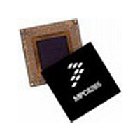
MPC8255ACZUMHBB Freescale Semiconductor, MPC8255ACZUMHBB Datasheet - Page 9

MPC8255ACZUMHBB
Manufacturer Part Number
MPC8255ACZUMHBB
Description
IC MPU POWERQUICC II 480-TBGA
Manufacturer
Freescale Semiconductor
Specifications of MPC8255ACZUMHBB
Processor Type
MPC82xx PowerQUICC II 32-bit
Speed
266MHz
Voltage
2V
Mounting Type
Surface Mount
Package / Case
480-TBGA
Family Name
MPC82XX
Device Core
PowerQUICC II
Device Core Size
32b
Frequency (max)
266MHz
Instruction Set Architecture
RISC
Supply Voltage 1 (typ)
2V
Operating Supply Voltage (max)
2.1V
Operating Supply Voltage (min)
1.9V
Operating Temp Range
-40C to 105C
Operating Temperature Classification
Industrial
Mounting
Surface Mount
Pin Count
480
Package Type
TBGA
Lead Free Status / RoHS Status
Contains lead / RoHS non-compliant
Features
-
Lead Free Status / Rohs Status
Not Compliant
Available stocks
Company
Part Number
Manufacturer
Quantity
Price
Company:
Part Number:
MPC8255ACZUMHBB
Manufacturer:
MOTOROLA
Quantity:
745
Company:
Part Number:
MPC8255ACZUMHBB
Manufacturer:
Freescale Semiconductor
Quantity:
10 000
Part Number:
MPC8255ACZUMHBB
Manufacturer:
FREESCALE
Quantity:
20 000
1.2.2
Table 4 describes thermal characteristics.
1.2.3
The average chip-junction temperature
where
For most applications P
is the following:
Solving equations (1) and (2) for K gives:
where K is a constant pertaining to the particular part. K can be determined from equation (3) by measuring
P
equations (1) and (2) iteratively for any value of T
1.2.3.1
Each V
should likewise be provided with a low-impedance path to ground. The power supply pins drive distinct
groups of logic on chip. The V
by-pass capacitors located as close as possible to the four sides of the package. The capacitor leads and
associated printed circuit traces connecting to chip V
per capacitor lead. A four-layer board is recommended, employing two inner layers as V
D
1
2
3
(at equilibrium) for a known T
Thermal resistance for TBGA
Assumes a single layer board with no thermal vias
Natural convection
Assumes a four layer board
CC
T
T
P
P
P
P
K = P
A
JA
D
INT
I/O
D
J
pin should be provided with a low-impedance path to the board’s power supply. Each ground pin
= T
= ambient temperature C
= P
= K/(T
Thermal Characteristics
Power Considerations
= package thermal resistance
= power dissipation on input and output pins (determined by user)
Characteristics
= I
Layout Practices
D
A
INT
DD
x (T
+ (P
J
+ P
x V
+ 273 C)
A
D
PRELIMINARY—SUBJECT TO CHANGE WITHOUT NOTICE
+ 273 C) +
I/O
x
DD
I/O
JA
Watts (chip internal power)
< 0.3 x P
Freescale Semiconductor, Inc.
)
For More Information On This Product,
CC
A
. Using this value of K
MPC8255 Hardware Specifications
power supply should be bypassed to ground using at least four 0.1 µF
INT
Table 4. Thermal Characteristics
JA
,
. If P
x P
Go to: www.freescale.com
T
,
J ,
junction to ambient
D
in C can be obtained from the following:
Symbol
I/O
2
JA
JA
is neglected
JA
JA
A
.
CC
and ground should be kept to less than half an inch
,
the values of P
,
an approximate relationship between P
13.07
10.48
Value
9.55
7.78
,
C/W
1
3
Electrical and Thermal Characteristics
1
3
D
and T
Unit
C/W
C/W
C/W
C/W
J
can be obtained by solving
CC
and GND planes.
Air Flow
1 m/s
1 m/s
NC
NC
2
D
and T
(2)
(1)
(3)
J


