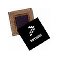
MPC8255ACZUMHBB Freescale Semiconductor, MPC8255ACZUMHBB Datasheet - Page 19

MPC8255ACZUMHBB
Manufacturer Part Number
MPC8255ACZUMHBB
Description
IC MPU POWERQUICC II 480-TBGA
Manufacturer
Freescale Semiconductor
Specifications of MPC8255ACZUMHBB
Processor Type
MPC82xx PowerQUICC II 32-bit
Speed
266MHz
Voltage
2V
Mounting Type
Surface Mount
Package / Case
480-TBGA
Family Name
MPC82XX
Device Core
PowerQUICC II
Device Core Size
32b
Frequency (max)
266MHz
Instruction Set Architecture
RISC
Supply Voltage 1 (typ)
2V
Operating Supply Voltage (max)
2.1V
Operating Supply Voltage (min)
1.9V
Operating Temp Range
-40C to 105C
Operating Temperature Classification
Industrial
Mounting
Surface Mount
Pin Count
480
Package Type
TBGA
Lead Free Status / RoHS Status
Contains lead / RoHS non-compliant
Features
-
Lead Free Status / Rohs Status
Not Compliant
Available stocks
Company
Part Number
Manufacturer
Quantity
Price
Company:
Part Number:
MPC8255ACZUMHBB
Manufacturer:
MOTOROLA
Quantity:
745
Company:
Part Number:
MPC8255ACZUMHBB
Manufacturer:
Freescale Semiconductor
Quantity:
10 000
Part Number:
MPC8255ACZUMHBB
Manufacturer:
FREESCALE
Quantity:
20 000
1
2
3
4
MODCK_H–MODCK[1–3]
Input clock frequency is given only for the purpose of reference. User should set MODCK_H–MODCK_L so that
Because of speed dependencies, not all of the possible configurations in Table 13 are applicable.
The user should choose the input clock frequency and the multiplication factors such that the frequency of the
At this mode the CPU PLL is bypassed (the CPU frequency equals the bus frequency).
CPU is equal to or greater than 133 MHz (150 MHz for extended temperature parts) and the CPM ranges
between 66–233 MHz.
the resulting configuration does not exceed the frequency rating of the user’s part.
Example. If a part is rated at 266 MHz CPU, 200 MHz CPM, and 66 MHz bus, any of the following are possible
(note that the three input clock frequencies are only three of many possible input clock frequencies):
1. 66 MHz input clock and MODCK_H–MODCK_L[0111–101] (with a core multiplication factor of 4 and a CPM
2. 50 MHz input clock and MODCK_H–MODCK_L[0111–101] to achieve a configuration of 200 MHz CPU,
3. 40 MHz input clock and MODCK_H–MODCK_L[0010–011] to achieve a configuration of 200 MHz CPU,
Note that with each example, any one of several values for MODCK_H–MODCK_L could possibly be used as
long as the resulting configuration does not exceed the part’s rating.
multiplication factor of 3). The resulting configuration equals the part’s maximum possible frequencies of
266 MHz CPU, 200 MHz CPM, and 66 MHz bus.
150 MHz CPM, and 50 MHz bus.
160 MHz CPM, and 40 MHz bus.
1100_000
1100_001
1100_010
1000_000
1000_001
1000_010
1000_100
0111_000
0111_001
0111_010
0111_100
0111_101
1000_011
0110_111
0111_011
0111_110
0111_111
4
4
4
PRELIMINARY—SUBJECT TO CHANGE WITHOUT NOTICE
Table 13. Clock Configuration Modes
Frequency
Input Clock
Freescale Semiconductor, Inc.
66 MHz
66 MHz
66 MHz
66 MHz
66 MHz
66 MHz
66 MHz
66 MHz
66 MHz
66 MHz
66 MHz
66 MHz
66 MHz
66 MHz
66 MHz
66 MHz
66 MHz
For More Information On This Product,
MPC8255 Hardware Specifications
2,3
Go to: www.freescale.com
CPM Multiplication
Factor
2.5
2.5
3.5
3.5
3.5
3.5
3.5
3.5
2.5
3
3
3
3
3
3
2
3
2
Frequency
166 MHz
166 MHz
200 MHz
200 MHz
200 MHz
200 MHz
200 MHz
200 MHz
233 MHz
233 MHz
233 MHz
233 MHz
233 MHz
233 MHz
133 MHz
166 MHz
200 MHz
CPM
1
(Continued)
2
Core Multiplication
Clock Configuration Modes
Factor
Bypass
Bypass
Bypass
4.5
2.5
3.5
4.5
2.5
3.5
4.5
4
2
3
4
2
3
4
2
Frequency
266 MHz
300 MHz
133 MHz
166 MHz
200 MHz
233 MHz
266 MHz
300 MHz
133 MHz
166 MHz
200 MHz
233 MHz
266 MHz
300 MHz
66 MHz
66 MHz
66 MHz
Core
2


