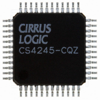
CS4245-CQZ Cirrus Logic Inc, CS4245-CQZ Datasheet - Page 5

CS4245-CQZ
Manufacturer Part Number
CS4245-CQZ
Description
IC CODEC AUD STER 104DB 48LQFP
Manufacturer
Cirrus Logic Inc
Type
Stereo Audior
Datasheet
1.CS4245-CQZ.pdf
(57 pages)
Specifications of CS4245-CQZ
Package / Case
48-LQFP
Data Interface
Serial
Resolution (bits)
24 b
Number Of Adcs / Dacs
2 / 2
Sigma Delta
Yes
Dynamic Range, Adcs / Dacs (db) Typ
104 / 104
Voltage - Supply, Analog
3.13 V ~ 5.25 V
Voltage - Supply, Digital
3.13 V ~ 5.25 V
Operating Temperature
-10°C ~ 70°C
Mounting Type
Surface Mount
Number Of Adc Inputs
12
Number Of Dac Outputs
4
Conversion Rate
192 KSPS
Interface Type
Serial (I2C, SPI)
Resolution
24 bit
Operating Supply Voltage
3.3 V, 5 V
Maximum Operating Temperature
+ 70 C
Mounting Style
SMD/SMT
Minimum Operating Temperature
- 10 C
Number Of Channels
2 ADC/2 DAC
Thd Plus Noise
- 95 dB ADC / - 90 dB DAC
Lead Free Status / RoHS Status
Lead free / RoHS Compliant
For Use With
598-1501 - BOARD EVAL FOR CS4245 CODEC
Lead Free Status / Rohs Status
Lead free / RoHS Compliant
Other names
598-1034
Available stocks
Company
Part Number
Manufacturer
Quantity
Price
Company:
Part Number:
CS4245-CQZ
Manufacturer:
CIRRUS
Quantity:
455
Part Number:
CS4245-CQZ
Manufacturer:
CIRRUS
Quantity:
20 000
Company:
Part Number:
CS4245-CQZR
Manufacturer:
Schneider
Quantity:
1 000
Company:
Part Number:
CS4245-CQZR
Manufacturer:
Cirrus Logic Inc
Quantity:
10 000
CS4245
Figure 2.Maximum DAC Loading .............................................................................................................. 11
Figure 3.Master Mode Timing - Serial Audio Port 1 .................................................................................. 22
Figure 4.Slave Mode Timing - Serial Audio Port 1 .................................................................................... 22
Figure 5.Master Mode Timing - Serial Audio Port 2 .................................................................................. 24
Figure 6.Slave Mode Timing - Serial Audio Port 2 .................................................................................... 24
Figure 7.Format 0, Left-Justified up to 24-Bit Data ................................................................................... 25
Figure 8.Format 1, I²S up to 24-Bit Data ................................................................................................... 25
Figure 9.Format 2, Right-Justified 16-Bit Data.
Format 3, Right-Justified 24-Bit Data. ....................................................................................................... 25
Figure 10.Control Port Timing - I²C Format ............................................................................................... 26
Figure 11.Control Port Timing - SPI Format .............................................................................................. 27
Figure 12.Typical Connection Diagram ..................................................................................................... 28
Figure 13.Master Mode Clocking .............................................................................................................. 30
Figure 14.Analog Input Architecture .......................................................................................................... 32
Figure 15.De-Emphasis Curve .................................................................................................................. 34
Figure 16.Suggested Active-Low Mute Circuit .......................................................................................... 35
Figure 17.Control Port Timing in SPI Mode .............................................................................................. 36
Figure 18.Control Port Timing, I²C Write ................................................................................................... 36
Figure 19.Control Port Timing, I²C Read ................................................................................................... 37
Figure 20.De-Emphasis Curve .................................................................................................................. 42
Figure 21.DAC Single-Speed Stopband Rejection ................................................................................... 51
Figure 22.DAC Single-Speed Transition Band .......................................................................................... 51
Figure 23.DAC Single-Speed Transition Band .......................................................................................... 51
Figure 24.DAC Single-Speed Passband Ripple ........................................................................................ 51
Figure 25.DAC Double-Speed Stopband Rejection .................................................................................. 51
Figure 26.DAC Double-Speed Transition Band ........................................................................................ 51
Figure 27.DAC Double-Speed Transition Band ........................................................................................ 52
Figure 28.DAC Double-Speed Passband Ripple ...................................................................................... 52
Figure 29.DAC Quad-Speed Stopband Rejection ..................................................................................... 52
Figure 30.DAC Quad-Speed Transition Band ........................................................................................... 52
Figure 31.DAC Quad-Speed Transition Band ........................................................................................... 52
Figure 32.DAC Quad-Speed Passband Ripple ......................................................................................... 52
Figure 33.ADC Single-Speed Stopband Rejection ................................................................................... 53
Figure 34.ADC Single-Speed Stopband Rejection ................................................................................... 53
Figure 35.ADC Single-Speed Transition Band (Detail) ............................................................................. 53
Figure 36.ADC Single-Speed Passband Ripple ........................................................................................ 53
Figure 37.ADC Double-Speed Stopband Rejection .................................................................................. 53
Figure 38.ADC Double-Speed Stopband Rejection .................................................................................. 53
Figure 39.ADC Double-Speed Transition Band (Detail) ............................................................................ 54
Figure 40.ADC Double-Speed Passband Ripple ...................................................................................... 54
Figure 41.ADC Quad-Speed Stopband Rejection ..................................................................................... 54
Figure 42.ADC Quad-Speed Stopband Rejection ..................................................................................... 54
Figure 43.ADC Quad-Speed Transition Band (Detail) .............................................................................. 54
Figure 44.ADC Quad-Speed Passband Ripple ......................................................................................... 54
LIST OF TABLES
Table 1. Speed Modes .............................................................................................................................. 29
Table 2. Common Clock Frequencies ....................................................................................................... 30
Table 3. Slave Mode Serial Bit Clock Ratios ............................................................................................. 31
Table 4. Device Revision .......................................................................................................................... 40
Table 5. Freeze-able Bits .......................................................................................................................... 40
Table 6. Functional Mode Selection ......................................................................................................... 41
Table 7. DAC Digital Interface Formats .................................................................................................... 41
DS656F2
5


