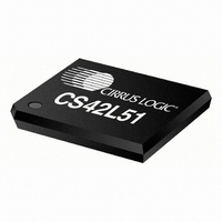
CS42L51-CNZ Cirrus Logic Inc, CS42L51-CNZ Datasheet - Page 20

CS42L51-CNZ
Manufacturer Part Number
CS42L51-CNZ
Description
IC CODEC STEREO W/HDPN AMP 32QFN
Manufacturer
Cirrus Logic Inc
Type
Stereo Audior
Datasheet
1.CS42L51-CNZ.pdf
(88 pages)
Specifications of CS42L51-CNZ
Package / Case
32-QFP
Data Interface
PCM Audio Interface
Resolution (bits)
24 b
Number Of Adcs / Dacs
2 / 2
Sigma Delta
Yes
Dynamic Range, Adcs / Dacs (db) Typ
98 / 98
Voltage - Supply, Analog
1.8V, 2.5V
Voltage - Supply, Digital
1.8V, 2.5V
Operating Temperature
-10°C ~ 70°C
Mounting Type
Surface Mount
Number Of Adc Inputs
6
Number Of Dac Outputs
2
Conversion Rate
96 KSPS
Interface Type
Serial (2-Wire, 3-Wire, I2C, SPI)
Resolution
24 bit
Operating Supply Voltage
1.8 V / 2.5 V
Maximum Operating Temperature
+ 70 C
Mounting Style
SMD/SMT
Minimum Operating Temperature
- 10 C
Number Of Channels
2 ADC/2 DAC
Thd Plus Noise
- 88 dB ADC / - 86 dB DAC
Peak Reflow Compatible (260 C)
No
Leaded Process Compatible
No
Rohs Compliant
Yes
Lead Free Status / RoHS Status
Lead free / RoHS Compliant
For Use With
598-1005 - BOARD EVAL FOR CS42L51 CODEC
Lead Free Status / Rohs Status
Lead free / RoHS Compliant
Other names
598-1045
Available stocks
Company
Part Number
Manufacturer
Quantity
Price
Company:
Part Number:
CS42L51-CNZ
Manufacturer:
CIRRUS
Quantity:
160
Company:
Part Number:
CS42L51-CNZ
Manufacturer:
CIRRUS
Quantity:
162
Part Number:
CS42L51-CNZ
Manufacturer:
CIRRUS
Quantity:
20 000
Company:
Part Number:
CS42L51-CNZR
Manufacturer:
Cirrus Logic Inc
Quantity:
10 000
20
COMBINED DAC INTERPOLATION & ON-CHIP ANALOG FILTER RESPONSE
Notes:
SWITCHING SPECIFICATIONS - SERIAL PORT
(Inputs: Logic 0 = DGND, Logic 1 = VL, SDOUT C
Frequency Response 10 Hz to 20 kHz
Passband
StopBand
StopBand Attenuation
Group Delay
De-emphasis Error
RESET
MCLK Frequency
MCLK Duty Cycle
Slave Mode
Input Sample Rate (LRCK)
LRCK Duty Cycle
SCLK Frequency
SCLK Duty Cycle
LRCK Setup Time Before SCLK Rising Edge
LRCK Edge to SDOUT MSB Output Delay
SDOUT Setup Time Before SCLK Rising Edge
SDOUT Hold Time After SCLK Rising Edge
SDIN Setup Time Before SCLK Rising Edge
SDIN Hold Time After SCLK Rising Edge
12. Response is clock dependent and will scale with Fs. Note that the response plots
13. Measurement Bandwidth is from Stopband to 3 Fs.
pin Low Pulse Width
on page
(Note 13)
82) have been normalized to Fs and can be de-normalized by multiplying the X-axis scale by Fs.
Parameter
Parameters
(Note 12)
LOAD
Quarter-Speed Mode
Double-Speed Mode
Single-Speed Mode
Half-Speed Mode
= 15 pF.)
to -0.05 dB corner
to -3 dB corner
Fs = 44.1 kHz
Fs = 32 kHz
Fs = 48 kHz
(Note 14)
(Note 15)
t
t
Symbol
s(SDO-SK)
h(SK-SDO)
t
t
s(SD-SK)
s(LK-SK)
t
0.5465
d(MSB)
-0.01
Min
1/t
F
F
F
F
50
t
0
0
-
-
-
-
h
s
s
s
s
P
10.4/Fs
1.024
Min
Typ
45
50
45
45
40
20
30
20
20
1
4
8
4
-
-
-
-
-
-
-
-
-
-
(Figure 38
+0.05/-0.25
-0.2/-0.4
+1.5/+0
64•F
Max
0.4780
0.4996
38.4
12.5
100
+0.08
Max
55
25
50
55
55
52
-
-
-
-
-
-
CS42L51
-
-
-
to
s
Figure 41
DS679F1
Units
MHz
kHz
kHz
kHz
kHz
Unit
ms
Hz
ns
ns
ns
ns
ns
ns
%
%
%
dB
dB
dB
dB
dB
Fs
Fs
Fs
s


