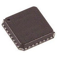
ADAU1381BCPZ Analog Devices Inc, ADAU1381BCPZ Datasheet - Page 28

ADAU1381BCPZ
Manufacturer Part Number
ADAU1381BCPZ
Description
IC AUDIO CODEC STEREO LN 32LFCSP
Manufacturer
Analog Devices Inc
Type
Stereo Audior
Datasheet
1.ADAU1381BCBZ-RL.pdf
(84 pages)
Specifications of ADAU1381BCPZ
Data Interface
Serial, SPI™
Resolution (bits)
24 b
Number Of Adcs / Dacs
2 / 2
Sigma Delta
No
S/n Ratio, Adcs / Dacs (db) Typ
97 / 100
Dynamic Range, Adcs / Dacs (db) Typ
96.5 / 100
Voltage - Supply, Analog
1.8 V ~ 3.65 V
Voltage - Supply, Digital
1.63 V ~ 3.65 V
Operating Temperature
-25°C ~ 85°C
Mounting Type
Surface Mount
Package / Case
32-VFQFN, CSP Exposed Pad
Audio Codec Type
Stereo
No. Of Adcs
2
No. Of Dacs
2
No. Of Input Channels
3
No. Of Output Channels
3
Adc / Dac Resolution
24bit
Adcs / Dacs Signal To Noise Ratio
100dB
Lead Free Status / RoHS Status
Lead free / RoHS Compliant
ADAU1381
Table 14 and Table 15 list the sampling rate divisions for
common base sampling rates.
Table 14. Base Sampling Rate Divisions for f
Base Sampling
Frequency
f
Table 15. Base Sampling Rate Divisions for f
Base Sampling
Frequency
f
PLL
The PLL uses the MCLK as a reference to generate the core
clock. PLL settings are set in Register 16386 (0x4002), PLL
control. Depending on the MCLK frequency, the PLL must be
set for either integer or fractional mode. The PLL can accept
input frequencies in the range of 11 MHz to 20 MHz.
All six bytes in the PLL control register must be written with a
single continuous write to the control port.
Integer Mode
Integer mode is used when the MCLK is an integer (R) multiple
of the PLL output (1024 × f
For example, if MCLK = 12.288 MHz and f
In integer mode, the values set for N and M are ignored.
S
S
= 48 kHz
= 44.1 kHz
PLL Required Output = 1024 × 48 kHz = 49.152 MHz
R = 49.152 MHz/12.288 MHz = 4
MCKI
Sampling Rate Scaling
f
f
f
f
f
f
f
Sampling Rate Scaling
f
f
f
f
f
f
f
S
S
S
S
S
S
S
S
S
S
S
S
S
S
Figure 30. PLL Block Diagram
/1
/6
/4
/3
/2
/1.5
/0.5
/1
/6
/4
/3
/2
/1.5
/0.5
÷ X
S
).
× (R + N/M)
CLOCK DIVIDER
TO PLL
S
= 48 kHz, then
Sampling Rate
48 kHz
8 kHz
12 kHz
16 kHz
24 kHz
32 kHz
96 kHz
Sampling Rate
44.1 kHz
7.35 kHz
11.025 kHz
14.7 kHz
22.05 kHz
29.4 kHz
88.2 kHz
S
S
= 48 kHz
= 44.1 kHz
Rev. B | Page 28 of 84
Fractional Mode
Fractional mode is used when the MCLK is a fractional
(R + (N/M)) multiple of the PLL output.
For example, if MCLK = 12 MHz and f
Common fractional PLL parameter settings for 44.1 kHz and
48 kHz sampling rates can be found in Table 16 and Table 17.
Table 16. Fractional PLL Parameter Settings for f
MCLK
Input
(MHz)
12
13
14.4
19.2
19.68
19.8
1
Table 17. Fractional PLL Parameter Settings for f
MCLK
Input
(MHz)
12
13
14.4
19.2
19.68
19.8
1
The PLL outputs a clock in the range of 41 MHz to 54 MHz,
which should be taken into account when calculating PLL
values and MCLK frequencies.
Desired core clock = 11.2896 MHz, PLL output = 45.1584 MHz.
Desired core clock = 12.288 MHz, PLL output = 49.152 MHz.
PLL Required Output = 1024 × 48 kHz = 49.152 MHz
R + (N/M) = 49.152 MHz/12 MHz = 4 + (12/125)
Input
Divider
(X)
1
1
2
2
2
2
Input
Divider
(X)
1
1
2
2
2
2
Integer
(R)
3
3
6
4
4
4
Integer
(R)
4
3
6
5
4
4
Denominator
(M)
625
8125
125
125
1025
1375
Denominator
(M)
125
1625
75
25
205
825
S
= 48 kHz, then
S
= 44.1 kHz
Numerator
(N)
477
3849
34
88
604
772
Numerator
(N)
12
1269
62
3
204
796
S
= 48 kHz
1
1


