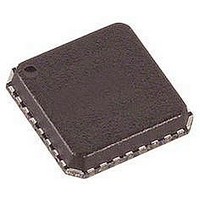
ADAU1381BCPZ Analog Devices Inc, ADAU1381BCPZ Datasheet - Page 53

ADAU1381BCPZ
Manufacturer Part Number
ADAU1381BCPZ
Description
IC AUDIO CODEC STEREO LN 32LFCSP
Manufacturer
Analog Devices Inc
Type
Stereo Audior
Datasheet
1.ADAU1381BCBZ-RL.pdf
(84 pages)
Specifications of ADAU1381BCPZ
Data Interface
Serial, SPI™
Resolution (bits)
24 b
Number Of Adcs / Dacs
2 / 2
Sigma Delta
No
S/n Ratio, Adcs / Dacs (db) Typ
97 / 100
Dynamic Range, Adcs / Dacs (db) Typ
96.5 / 100
Voltage - Supply, Analog
1.8 V ~ 3.65 V
Voltage - Supply, Digital
1.63 V ~ 3.65 V
Operating Temperature
-25°C ~ 85°C
Mounting Type
Surface Mount
Package / Case
32-VFQFN, CSP Exposed Pad
Audio Codec Type
Stereo
No. Of Adcs
2
No. Of Dacs
2
No. Of Input Channels
3
No. Of Output Channels
3
Adc / Dac Resolution
24bit
Adcs / Dacs Signal To Noise Ratio
100dB
Lead Free Status / RoHS Status
Lead free / RoHS Compliant
SERIAL PORT CONFIGURATION
Register 16405 (0x4015), Serial Port Control 0
Bit 5, LRCLK Mode
This bit sets the serial port frame clock (LRCLK) as either a
50% duty cycle waveform or a pulse synchronization waveform.
When in slave mode, the pulse should be at least 1 BCLK cycle
wide to guarantee proper data transfer.
Bit 4, BCLK Polarity
This bit sets the polarity of the bit clock (BCLK) signal. This
setting determines whether the data and frame clock signals
change on a rising (+) or falling (−) edge of the BCLK signal
(see Figure 57). Standard I
Bit 3, LRCLK Polarity
The polarity of LRCLK determines whether the left stereo channel
is initiated on a rising (+) or falling (−) edge of the LRCLK signal
(see Figure 58). Standard I
Table 40. Serial Port Control 0 Register
Bits
[7:6]
5
4
3
[2:1]
0
Description
Reserved
LRCLK mode
0: 50% duty cycle clock
1: pulse mode; pulse should be at least 1 BCLK wide
BCLK polarity
0: data changes on falling (−) edge
1: data changes on rising (+) edge
LRCLK polarity
0: left frame starts on falling (−) edge
1: left frame starts on rising (+) edge
Channels per frame
00: stereo (two channels)
01: TDM 4 (four channels)
10: TDM 8 (eight channels)
11: reserved
Serial data port mode
0: slave
1: master
2
S signals use negative LRCLK polarity.
2
S signals use negative BCLK polarity.
Rev. B | Page 53 of 84
Bits[2:1], Channels per Frame
These bits set the number of channels contained in the data stream
(see Figure 59). The possible choices are stereo (used in standard
I
or TDM 8 (an 8-channel time division multiplexed stream). The
TDM output modes are simply multichannel data streams, and
the data pin does not become high impedance during periods
when it is not outputting data.
Within a TDM stream, channels are grouped by pair, as shown
in Figure 60.
Bit 0, Serial Data Port Mode
This bit sets the clock pins as either master or slave. Both
LRCLK and BCLK are the bus master of the serial port when
master mode is enabled.
2
S signals), TDM 4 (a 4-channel time division multiplexed stream),
Default
0
0
0
00
0
ADAU1381


