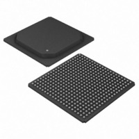
DS33R41+ Maxim Integrated Products, DS33R41+ Datasheet - Page 12

DS33R41+
Manufacturer Part Number
DS33R41+
Description
IC TXRX ETHERNET MAP 400-BGA
Manufacturer
Maxim Integrated Products
Type
Transceiverr
Datasheet
1.DS33R41.pdf
(335 pages)
Specifications of DS33R41+
Number Of Drivers/receivers
4/4
Protocol
T1/E1/J1
Voltage - Supply
3.14 V ~ 3.47 V
Mounting Type
Surface Mount
Package / Case
400-BGA
Lead Free Status / RoHS Status
Lead free / RoHS Compliant
- Current page: 12 of 335
- Download datasheet (2Mb)
2.6 Additional HDLC Controllers in the Integrated T1/E1/J1 Transceiver
2.7 Committed Information Rate (CIR) Controllers
2.8 SDRAM Interface
2.9 T1/E1/J1 Framer
•
•
•
•
•
•
•
•
•
•
•
•
•
•
•
•
•
•
•
•
•
•
•
•
•
•
•
•
•
•
•
•
•
•
•
•
•
•
•
•
•
•
•
•
Two additional independent HDLC controllers
Fast load and unload features for FIFOs
SS7 support for FISU transmit and receive
Independent 128-byte Rx and Tx buffers with interrupt support
Access FDL, Sa, or single/multiple DS0 channels
DS0 access includes Nx64 or Nx56
Compatible with polled or interrupt driven environments
Bit-oriented code (BOC) support
CIR controller limits transmission of data from the Ethernet Interface to the serial interface
CIR granularity at 512kbps
CIR Averaging for smoothing traffic peaks
Interface for 128Mbit, 32-bit wide SDRAM
SDRAM Interface speed up to 100MHz
Auto refresh timing
Automatic precharge
Master clock provided to the SDRAM
No external components required for SDRAM connectivity
Fully independent transmit and receive functionality
Full receive- and transmit-path transparency
T1 framing formats include D4, ESF, J1-D4, J1-ESF and SLC-96
Japanese J1 support for CRC6 and yellow alarm
E1 framing formats include FAS, CAS, and CRC-4
Detailed alarm- and status-reporting with optional interrupt support
Large path- and line-error counters for:
T1—BPV, CV, CRC6, and framing bit errors
E1—BPV, CV, CRC-4, E-bit, and frame alignment errors
Timed or manual update modes
User-defined Idle Code Generation on a per-channel basis in both transmit and receive paths
Digital milliwatt code generation on the receive path
ANSI T1.403-1998 support
G.965 V5.2 link detect
RAI-CI, AIS-CI detection and generation
Ability to monitor one DS0 channel in both the transmit and receive paths
Three independent, In-band repeating-pattern generators and detectors
Patterns from 1 bit to 8 bits or 16 bits in length
RCL, RLOS, RRA, and RAIS alarms interrupt on change of state
Flexible signaling support
Software- or hardware-based
Interrupt generated on change of signaling data
Receive-signaling freeze on loss of sync, carrier loss, or frame slip
Hardware pins to indicate carrier loss and signaling freeze
Automatic RAI generation to ETS 300 011 specifications
Expanded access to Sa and Si bits
Option to extend carrier-loss criteria to a 1ms period as per ETS 300 233
12 of 335
Related parts for DS33R41+
Image
Part Number
Description
Manufacturer
Datasheet
Request
R

Part Number:
Description:
MAX7528KCWPMaxim Integrated Products [CMOS Dual 8-Bit Buffered Multiplying DACs]
Manufacturer:
Maxim Integrated Products
Datasheet:

Part Number:
Description:
Single +5V, fully integrated, 1.25Gbps laser diode driver.
Manufacturer:
Maxim Integrated Products
Datasheet:

Part Number:
Description:
Single +5V, fully integrated, 155Mbps laser diode driver.
Manufacturer:
Maxim Integrated Products
Datasheet:

Part Number:
Description:
VRD11/VRD10, K8 Rev F 2/3/4-Phase PWM Controllers with Integrated Dual MOSFET Drivers
Manufacturer:
Maxim Integrated Products
Datasheet:

Part Number:
Description:
Highly Integrated Level 2 SMBus Battery Chargers
Manufacturer:
Maxim Integrated Products
Datasheet:

Part Number:
Description:
Current Monitor and Accumulator with Integrated Sense Resistor; ; Temperature Range: -40°C to +85°C
Manufacturer:
Maxim Integrated Products

Part Number:
Description:
TSSOP 14/A�/RS-485 Transceivers with Integrated 100O/120O Termination Resis
Manufacturer:
Maxim Integrated Products

Part Number:
Description:
TSSOP 14/A�/RS-485 Transceivers with Integrated 100O/120O Termination Resis
Manufacturer:
Maxim Integrated Products

Part Number:
Description:
QFN 16/A�/AC-DC and DC-DC Peak-Current-Mode Converters with Integrated Step
Manufacturer:
Maxim Integrated Products

Part Number:
Description:
TDFN/A/65V, 1A, 600KHZ, SYNCHRONOUS STEP-DOWN REGULATOR WITH INTEGRATED SWI
Manufacturer:
Maxim Integrated Products

Part Number:
Description:
Integrated Temperature Controller f
Manufacturer:
Maxim Integrated Products

Part Number:
Description:
SOT23-6/I�/45MHz to 650MHz, Integrated IF VCOs with Differential Output
Manufacturer:
Maxim Integrated Products

Part Number:
Description:
SOT23-6/I�/45MHz to 650MHz, Integrated IF VCOs with Differential Output
Manufacturer:
Maxim Integrated Products

Part Number:
Description:
EVALUATION KIT/2.4GHZ TO 2.5GHZ 802.11G/B RF TRANSCEIVER WITH INTEGRATED PA
Manufacturer:
Maxim Integrated Products

Part Number:
Description:
QFN/E/DUAL PCIE/SATA HIGH SPEED SWITCH WITH INTEGRATED BIAS RESISTOR
Manufacturer:
Maxim Integrated Products
Datasheet:


