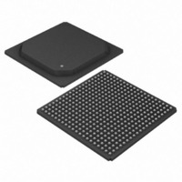
DS33R41+ Maxim Integrated Products, DS33R41+ Datasheet - Page 26

DS33R41+
Manufacturer Part Number
DS33R41+
Description
IC TXRX ETHERNET MAP 400-BGA
Manufacturer
Maxim Integrated Products
Type
Transceiverr
Datasheet
1.DS33R41.pdf
(335 pages)
Specifications of DS33R41+
Number Of Drivers/receivers
4/4
Protocol
T1/E1/J1
Voltage - Supply
3.14 V ~ 3.47 V
Mounting Type
Surface Mount
Package / Case
400-BGA
Lead Free Status / RoHS Status
Lead free / RoHS Compliant
- Current page: 26 of 335
- Download datasheet (2Mb)
TSYSCLK1
TSYSCLK2
TSYSCLK3
TSYSCLK4
TSSYNC1
TSSYNC2
TSSYNC3
TSSYNC4
TCHCLK1
TCHCLK2
TCHCLK3
TCHCLK4
TCHBLK1
TCHBLK2
TCHBLK3
TCHBLK4
TSYNC1
TSYNC2
TSYNC3
TSYNC4
TCLKT1
TCLKT2
TCLKT3
TCLKT4
TRING4
TSERI1
TSERI2
TSERI3
TSERI4
NAME
TSIG1
TSIG2
TSIG3
TSIG4
DS33R41 Inverse-Multiplexing Ethernet Mapper with Quad Integrated T1/E1/J1 Transceivers
W9, Y9
E13
N13
A14
P11
C13
D13
PIN
W4
W3
R7
H4
U4
N9
M4
D3
C2
H2
Y4
B9
A6
Y5
A2
A9
Y3
E3
P6
V5
B8
P7
J2
J5
J3
L9
T1/E1/J1 TRANSMIT FRAMER INTERFACE
TYPE
I/O
O
O
O
I
I
I
I
I
Transmit Analog Ring Output for Transceiver 4. Analog line-driver
outputs. Two connections are provided to improve signal quality. These
pins connect via a 1:2 step-up transformer to the network. See Section
for details.
Transmit Serial Data for Transceivers 1–4. Transmit NRZ serial data.
Sampled on the falling edge of TCLKT when the transmit-side elastic
store is disabled. Sampled on the falling edge of TSYSCLK when the
transmit-side elastic store is enabled.
Transmit System Clock for Transceivers 1–4. 8.192MHz clock used for
Interleaved Bus Operation. Used when the transmit-side elastic-store
function is enabled. See the Interleaved PCM Bus Operation section for
details on 8.192MHz operation using the IBO.
Transmit System Sync for Transceivers 1–4. Only used when the
transmit-side elastic store is enabled. A pulse at this pin will establish
either frame or multiframe boundaries for the transmit side. Should be tied
low in applications that do not use the transmit-side elastic store.
Transmit Clock for Transceivers 1–4. 1.544MHz or a 2.048MHz
primary clock. Used to clock data through the transmit-side formatter. Not
used for most DS33R41 applications.
Transmit Channel Block for Transceivers 1–4. A user-programmable
output that can be forced high or low during any of the channels.
Synchronous with TSYSCLK when the transmit-side elastic store is
enabled. Useful for locating individual channels in drop-and-insert
applications, for external per-channel loopback, and for per-channel
conditioning.
Transmit Channel Clock for Transceivers 1–4. A 192kHz (T1) or
256kHz (E1) clock that pulses high during the LSB of each channel. Can
also be programmed to output a gated transmit-bit clock for fractional
T1/E1 applications. Synchronous with TSYSCLK when the transmit-side
elastic store is enabled. Useful for parallel-to-serial conversion of channel
data.
Transmit Sync for Transceivers 1–4. A pulse at this pin will establish
either frame or multiframe boundaries for the transmit side. Can be
programmed to output either a frame or multiframe pulse. If this pin is set
to output pulses at frame boundaries, it can also be set via IOCR1.3 to
output double-wide pulses at signaling frames in T1 mode.
Transmit Signaling Input for Transceivers 1–4. When enabled, this
input will sample signaling bits for insertion into outgoing PCM data
stream. Sampled on the falling edge of TCLKT when the transmit-side
elastic store is disabled. Sampled on the falling edge of TSYSCLK when
the transmit-side elastic store is enabled.
26 of 335
FUNCTION
10
Related parts for DS33R41+
Image
Part Number
Description
Manufacturer
Datasheet
Request
R

Part Number:
Description:
MAX7528KCWPMaxim Integrated Products [CMOS Dual 8-Bit Buffered Multiplying DACs]
Manufacturer:
Maxim Integrated Products
Datasheet:

Part Number:
Description:
Single +5V, fully integrated, 1.25Gbps laser diode driver.
Manufacturer:
Maxim Integrated Products
Datasheet:

Part Number:
Description:
Single +5V, fully integrated, 155Mbps laser diode driver.
Manufacturer:
Maxim Integrated Products
Datasheet:

Part Number:
Description:
VRD11/VRD10, K8 Rev F 2/3/4-Phase PWM Controllers with Integrated Dual MOSFET Drivers
Manufacturer:
Maxim Integrated Products
Datasheet:

Part Number:
Description:
Highly Integrated Level 2 SMBus Battery Chargers
Manufacturer:
Maxim Integrated Products
Datasheet:

Part Number:
Description:
Current Monitor and Accumulator with Integrated Sense Resistor; ; Temperature Range: -40°C to +85°C
Manufacturer:
Maxim Integrated Products

Part Number:
Description:
TSSOP 14/A�/RS-485 Transceivers with Integrated 100O/120O Termination Resis
Manufacturer:
Maxim Integrated Products

Part Number:
Description:
TSSOP 14/A�/RS-485 Transceivers with Integrated 100O/120O Termination Resis
Manufacturer:
Maxim Integrated Products

Part Number:
Description:
QFN 16/A�/AC-DC and DC-DC Peak-Current-Mode Converters with Integrated Step
Manufacturer:
Maxim Integrated Products

Part Number:
Description:
TDFN/A/65V, 1A, 600KHZ, SYNCHRONOUS STEP-DOWN REGULATOR WITH INTEGRATED SWI
Manufacturer:
Maxim Integrated Products

Part Number:
Description:
Integrated Temperature Controller f
Manufacturer:
Maxim Integrated Products

Part Number:
Description:
SOT23-6/I�/45MHz to 650MHz, Integrated IF VCOs with Differential Output
Manufacturer:
Maxim Integrated Products

Part Number:
Description:
SOT23-6/I�/45MHz to 650MHz, Integrated IF VCOs with Differential Output
Manufacturer:
Maxim Integrated Products

Part Number:
Description:
EVALUATION KIT/2.4GHZ TO 2.5GHZ 802.11G/B RF TRANSCEIVER WITH INTEGRATED PA
Manufacturer:
Maxim Integrated Products

Part Number:
Description:
QFN/E/DUAL PCIE/SATA HIGH SPEED SWITCH WITH INTEGRATED BIAS RESISTOR
Manufacturer:
Maxim Integrated Products
Datasheet:


