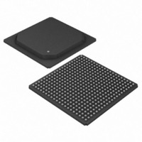
DS33R41+ Maxim Integrated Products, DS33R41+ Datasheet - Page 85

DS33R41+
Manufacturer Part Number
DS33R41+
Description
IC TXRX ETHERNET MAP 400-BGA
Manufacturer
Maxim Integrated Products
Type
Transceiverr
Datasheet
1.DS33R41.pdf
(335 pages)
Specifications of DS33R41+
Number Of Drivers/receivers
4/4
Protocol
T1/E1/J1
Voltage - Supply
3.14 V ~ 3.47 V
Mounting Type
Surface Mount
Package / Case
400-BGA
Lead Free Status / RoHS Status
Lead free / RoHS Compliant
- Current page: 85 of 335
- Download datasheet (2Mb)
10.10.1 Idle-Code Programming Examples
Example 1
Sets transmit channel 3 idle code to 7Eh.
Write TR.IAAR = 02h
Write TR.PCICR = 7Eh
Example 2
Sets transmit channels 3, 4, 5, and 6 idle code to 7Eh and enables transmission of idle codes for those channels.
Write TR.IAAR = 02h
Write TR.PCICR = 7Eh
Write TR.PCICR = 7Eh
Write TR.PCICR = 7Eh
Write TR.PCICR = 7Eh
Write TR.TCICE1 = 3Ch ;enable transmission of idle codes for channels 3,4,5, and 6
Example 3
Sets transmit channels 3, 4, 5, and 6 idle code to 7Eh, EEh, FFh, and 7Eh, respectively.
Write TR.IAAR = 02h
Write TR.PCICR = 7Eh
Write TR.PCICR = EEh
Write TR.PCICR = FFh
Write TR.PCICR = 7Eh
Example 4
Sets all transmit idle codes to 7Eh.
Write TR.IAAR = 4xh
Write TR.PCICR = 7Eh
Example 5
Sets all receive and transmit idle codes to 7Eh and enables idle code substitution in all E1 transmit and receive
channels.
Write TR.IAAR = Cxh
Write TR.PCICR = 7Eh
Write TR.TCICE1 = FEh ;enable idle code substitution for transmit channels 2 through 8
Write TR.TCICE2 = FFh ;enable idle code substitution for transmit channels 9 through 16
Write TR.TCICE3 = FEh ;enable idle code substitution for transmit channels 18 through 24
Write TR.TCICE4 = FFh ;enable idle code substitution for transmit channels 25 through 32
Write TR.RCICE1 = FEh ;enable idle code substitution for receive channels 2 through 8
Write TR.RCICE2 = FFh ;enable idle code substitution for receive channels 9 through 16
Write TR.RCICE3 = FEh ;enable idle code substitution for receive channels 18 through 24
Write TR.RCICE4 = FFh ;enable idle code substitution for receive channels 25 through 32
The transmit-channel idle-code enable registers (TR.TCICE1/2/3/4) are used to determine which of the 24 T1 or 32
E1 channels from the backplane to the T1 or E1 line should be overwritten with the code placed in the per-channel
code array.
The receive-channel idle-code enable registers (TR.RCICE1/2/3/4) are used to determine which of the 24 T1 or 32
E1 channels from the backplane to the T1 or E1 line should be overwritten with the code placed in the per-channel
code array.
;select channel 3 in the array
;set idle code to 7Eh
;select channel 3 in the array
;set channel 3 idle code to 7Eh
;set channel 4 idle code to 7Eh
;set channel 5 idle code to 7Eh
;set channel 6 idle code to 7Eh
;enable block write to all transmit and receive positions in the array
;7Eh is idle code
;Although an idle code was programmed for channel 1 by the block write
;function above, enabling it for channel 1 would step on the frame
;alignment, alarms, and Sa bits
;Although an idle code was programmed for channel 17 by the block write
;function above, enabling it for channel 17 would step on the CAS frame
;alignment, and signaling information
85 of 335
Related parts for DS33R41+
Image
Part Number
Description
Manufacturer
Datasheet
Request
R

Part Number:
Description:
MAX7528KCWPMaxim Integrated Products [CMOS Dual 8-Bit Buffered Multiplying DACs]
Manufacturer:
Maxim Integrated Products
Datasheet:

Part Number:
Description:
Single +5V, fully integrated, 1.25Gbps laser diode driver.
Manufacturer:
Maxim Integrated Products
Datasheet:

Part Number:
Description:
Single +5V, fully integrated, 155Mbps laser diode driver.
Manufacturer:
Maxim Integrated Products
Datasheet:

Part Number:
Description:
VRD11/VRD10, K8 Rev F 2/3/4-Phase PWM Controllers with Integrated Dual MOSFET Drivers
Manufacturer:
Maxim Integrated Products
Datasheet:

Part Number:
Description:
Highly Integrated Level 2 SMBus Battery Chargers
Manufacturer:
Maxim Integrated Products
Datasheet:

Part Number:
Description:
Current Monitor and Accumulator with Integrated Sense Resistor; ; Temperature Range: -40°C to +85°C
Manufacturer:
Maxim Integrated Products

Part Number:
Description:
TSSOP 14/A�/RS-485 Transceivers with Integrated 100O/120O Termination Resis
Manufacturer:
Maxim Integrated Products

Part Number:
Description:
TSSOP 14/A�/RS-485 Transceivers with Integrated 100O/120O Termination Resis
Manufacturer:
Maxim Integrated Products

Part Number:
Description:
QFN 16/A�/AC-DC and DC-DC Peak-Current-Mode Converters with Integrated Step
Manufacturer:
Maxim Integrated Products

Part Number:
Description:
TDFN/A/65V, 1A, 600KHZ, SYNCHRONOUS STEP-DOWN REGULATOR WITH INTEGRATED SWI
Manufacturer:
Maxim Integrated Products

Part Number:
Description:
Integrated Temperature Controller f
Manufacturer:
Maxim Integrated Products

Part Number:
Description:
SOT23-6/I�/45MHz to 650MHz, Integrated IF VCOs with Differential Output
Manufacturer:
Maxim Integrated Products

Part Number:
Description:
SOT23-6/I�/45MHz to 650MHz, Integrated IF VCOs with Differential Output
Manufacturer:
Maxim Integrated Products

Part Number:
Description:
EVALUATION KIT/2.4GHZ TO 2.5GHZ 802.11G/B RF TRANSCEIVER WITH INTEGRATED PA
Manufacturer:
Maxim Integrated Products

Part Number:
Description:
QFN/E/DUAL PCIE/SATA HIGH SPEED SWITCH WITH INTEGRATED BIAS RESISTOR
Manufacturer:
Maxim Integrated Products
Datasheet:


