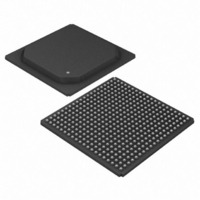
DS33R41+ Maxim Integrated Products, DS33R41+ Datasheet - Page 259

DS33R41+
Manufacturer Part Number
DS33R41+
Description
IC TXRX ETHERNET MAP 400-BGA
Manufacturer
Maxim Integrated Products
Type
Transceiverr
Datasheet
1.DS33R41.pdf
(335 pages)
Specifications of DS33R41+
Number Of Drivers/receivers
4/4
Protocol
T1/E1/J1
Voltage - Supply
3.14 V ~ 3.47 V
Mounting Type
Surface Mount
Package / Case
400-BGA
Lead Free Status / RoHS Status
Lead free / RoHS Compliant
- Current page: 259 of 335
- Download datasheet (2Mb)
Register Name:
Register Description:
Register Address:
Bit #
Name
Default
Bit 7: Number of Flags Select (NOFS)
Bit 6: Transmit End of Message and Loop (TEOML). To loop on a message, this bit should be set to a 1 just
before the last data byte of an HDLC packet is written into the transmit FIFO. The message repeats until the user
clears this bit or a new message is written to the transmit FIFO. If the host clears the bit, the looping message
completes, then flags are transmitted until a new message is written to the FIFO. If the host terminates the loop by
writing a new message to the FIFO, the loop terminates, one or two flags are transmitted, and the new message
starts. If not disabled through TCRCD, the transmitter automatically appends a 2-byte CRC code to the end of all
messages. This is useful for transmitting consecutive SS7 FISUs without host intervention.
Bit 5: Transmit HDLC Reset (THR). Resets the transmit HDLC controller and flushes the transmit FIFO. An abort
followed by 7Eh or FFh flags/idle is transmitted until a new packet is initiated by writing new data into the FIFO.
Must be cleared and set again for a subsequent reset.
Bit 4: Transmit HDLC Mapping Select (THMS)
Bit 3: Transmit Flag/Idle Select (TFS). This bit selects the intermessage fill character after the closing and before
the opening flags (7Eh).
Bit 2: Transmit End of Message (TEOM). Should be set to a 1 just before the last data byte of an HDLC packet is
written into the transmit FIFO at HxTF. If not disabled through TCRCD, the transmitter automatically appends a 2-
byte CRC code to the end of the message.
Bit 1: Transmit Zero-Stuffer Defeat (TZSD). The zero-stuffer function automatically inserts a 0 in the message
field (between the flags) after five consecutive 1s to prevent the emulation of a flag or abort sequence by the data
pattern. The receiver automatically removes (destuffs) any 0 after five 1s in the message field.
Bit 0: Transmit CRC Defeat (TCRCD). A 2-byte CRC code is automatically appended to the outbound message.
This bit can be used to disable the CRC function.
0 = send one flag between consecutive messages
1 = send two flags between consecutive messages
0 = normal operation
1 = reset transmit HDLC controller and flush the transmit FIFO
0 = transmit HDLC assigned to channels
1 = transmit HDLC assigned to FDL (T1 mode), Sa bits (E1 mode)
0 = 7Eh
1 = FFh
0 = enable the zero stuffer (normal operation)
1 = disable the zero stuffer
0 = enable CRC generation (normal operation)
1 = disable CRC generation
NOFS
7
0
TR.H1TC, TR.H2TC
HDLC #1 Transmit Control
HDLC #2 Transmit Control
90h, A0h
TEOML
6
0
THR
5
0
259 of 335
THMS
4
0
TFS
3
0
TEOM
2
0
TZSD
1
0
TCRCD
0
0
Related parts for DS33R41+
Image
Part Number
Description
Manufacturer
Datasheet
Request
R

Part Number:
Description:
MAX7528KCWPMaxim Integrated Products [CMOS Dual 8-Bit Buffered Multiplying DACs]
Manufacturer:
Maxim Integrated Products
Datasheet:

Part Number:
Description:
Single +5V, fully integrated, 1.25Gbps laser diode driver.
Manufacturer:
Maxim Integrated Products
Datasheet:

Part Number:
Description:
Single +5V, fully integrated, 155Mbps laser diode driver.
Manufacturer:
Maxim Integrated Products
Datasheet:

Part Number:
Description:
VRD11/VRD10, K8 Rev F 2/3/4-Phase PWM Controllers with Integrated Dual MOSFET Drivers
Manufacturer:
Maxim Integrated Products
Datasheet:

Part Number:
Description:
Highly Integrated Level 2 SMBus Battery Chargers
Manufacturer:
Maxim Integrated Products
Datasheet:

Part Number:
Description:
Current Monitor and Accumulator with Integrated Sense Resistor; ; Temperature Range: -40°C to +85°C
Manufacturer:
Maxim Integrated Products

Part Number:
Description:
TSSOP 14/A�/RS-485 Transceivers with Integrated 100O/120O Termination Resis
Manufacturer:
Maxim Integrated Products

Part Number:
Description:
TSSOP 14/A�/RS-485 Transceivers with Integrated 100O/120O Termination Resis
Manufacturer:
Maxim Integrated Products

Part Number:
Description:
QFN 16/A�/AC-DC and DC-DC Peak-Current-Mode Converters with Integrated Step
Manufacturer:
Maxim Integrated Products

Part Number:
Description:
TDFN/A/65V, 1A, 600KHZ, SYNCHRONOUS STEP-DOWN REGULATOR WITH INTEGRATED SWI
Manufacturer:
Maxim Integrated Products

Part Number:
Description:
Integrated Temperature Controller f
Manufacturer:
Maxim Integrated Products

Part Number:
Description:
SOT23-6/I�/45MHz to 650MHz, Integrated IF VCOs with Differential Output
Manufacturer:
Maxim Integrated Products

Part Number:
Description:
SOT23-6/I�/45MHz to 650MHz, Integrated IF VCOs with Differential Output
Manufacturer:
Maxim Integrated Products

Part Number:
Description:
EVALUATION KIT/2.4GHZ TO 2.5GHZ 802.11G/B RF TRANSCEIVER WITH INTEGRATED PA
Manufacturer:
Maxim Integrated Products

Part Number:
Description:
QFN/E/DUAL PCIE/SATA HIGH SPEED SWITCH WITH INTEGRATED BIAS RESISTOR
Manufacturer:
Maxim Integrated Products
Datasheet:


