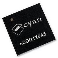
ECOG1X5A5L CYAN, ECOG1X5A5L Datasheet - Page 22

ECOG1X5A5L
Manufacturer Part Number
ECOG1X5A5L
Description
MCU, 16BIT, 512K FLASH, USB, 68QFN
Manufacturer
CYAN
Datasheet
1.ECOG1X5A5L.pdf
(95 pages)
Specifications of ECOG1X5A5L
Core Size
16bit
No. Of I/o's
32
Program Memory Size
512KB
Ram Memory Size
24KB
Cpu Speed
70MHz
Oscillator Type
External, Internal
No. Of Timers
5
No. Of Pwm Channels
2
Rohs Compliant
Yes
Controller Family/series
ECOG1X
Version 1.17
Interrupts
22
After power on or a hardware reset, execution starts from code space address zero mapped into the
internal flash memory. The first four words of code space should contain an instruction to branch to the
start of the application code.
The eCOG1X CPU supports 64 vectored interrupts and exceptions. The interrupt vector table follows
immediately after the eight bytes containing the reset vector branch instruction. Each vector contains a
16-bit offset. When an interrupt occurs, the interrupt service routine address is found by reading the
corresponding 16-bit vector offset and sign-extending it to a 25-bit code space address. It follows that
all interrupt service routines must be located in the first 64K bytes (address range 0x0000000 to
0x000FFFF) or last 64K bytes (address range 0x1FF0000 to 0x1FFFFFF) of code space.
Address
0x00 to
0x07
0x08
0x0A
0x0C
0x0E
0x10
0x12
0x14
0x16
0x18
0x1A
0x1C
0x1E
0x20
0x22
0x24
0x26
0x28
0x2A
0x2C
0x2E
0x30
0x32
0x34
0x36
0x38
0x3A
0x3C
0x3E
0x40
0x42
0x44
0x46
0x48
0x4A
0x4C
0x4E
0x50
0x52
0x54
Interrupt
reset
_ex_debug
_ex_wdog_exp
_ex_adr_err
_ex_reserved
_ex_tim
_ex_v33
_ex_usarta
_ex_usartb
_ex_uart1a
_ex_uart1b
_ex_uart2a
_ex_uart2b
_int_tmr_exp
_int_cnt1_exp
_int_cnt2_exp
_int_cnt1_match
_int_cnt2_match
_int_pwm1_exp
_int_pwm2_exp
_int_pwm1_match
_int_pwm2_match
_int_cap_exp
_int_cap1
_int_cap2
_int_cap3
_int_cap4
_int_cap5
_int_cap6
_int_ltmr_exp
_int_espi
_int_emac
_int_mcpwm
_int_usb_core
_int_usb_wakeup
_int_usb_fifo
_int_usb_dma
_int_aci
_int_i2s
_int_usarta_rx_rdy
eCOG and CyanIDE are registered trademarks of Cyan Holdings plc
eCOG1X Microcontroller Product Family
Source
Reset vector at location 0x0.
User must insert a branch instruction at this address.
Debug exception
Timer/counters, watchdog timer expired
MMU: access to an unmapped address
EMI: access to a chip select that is disabled
Exception interrupt from timer/counter module
Exception interrupt from VDD 3.3V sense
Exception interrupt from DUSART channel A
Exception interrupt from DUSART channel B
Exception interrupt from DUART1 channel A
Exception interrupt from DUART1 channel B
Exception interrupt from DUART2 channel A
Exception interrupt from DUART2 channel B
Timer/counters, timer TMR underflow
Timer/counters, counter CNT1 underflow
Timer/counters, counter CNT2 underflow
Timer/counters, counter CNT1 comparator match
Timer/counters, counter CNT2 comparator match
Timer/counters, PWM1 underflow
Timer/counters, PWM2 underflow
Timer/counters, PWM1 transition value match
Timer/counters, PWM2 transition value match
Timer/counters, input capture timer overflow
Timer/counters, input capture timer event 1
Timer/counters, input capture timer event 2
Timer/counters, input capture timer event 3
Timer/counters, input capture timer event 4
Timer/counters, input capture timer event 5
Timer/counters, input capture timer event 6
Timer/counters, long interval timer LTMR underflow
ESPI interrupts, tx ready, rx ready
Ethernet MAC interrupts
MCPWM interrupts, period, transition
USB core interrupts
USB wakeup event interrupt
USB FIFO interrupts
USB DMA interrupts
ACI module, ADC/DAC ready (conversion complete)
I
DUSART channel A receive port ready
2
S port interrupts
www.cyantechnology.com
Table 17: Interrupt vectors
11 February 2010


